|
3. SIMULATOR CONCEPT AND MODELS
Development of a dedicated AH simulator is a huge step forward for education and training, as well as R&D in offshore operation. The significant cost of such a commitment means that many actors need to take part in financing the project. It is therefore very important to find the best and most flexible concept, utilizing functionality for intensive use. To accomplish this goal we have incorporated functionality for conventional navigation and shiphandling as well. Therefore an integration with the existing shiphandling and DP simulators is essential. It is also important that the layout and instrumentation of the bridge is as identical as possible to the bridges found onboard modern AH vessels.
3.1 Requirements and Integration
To maintain the demand of flexibility we have decided to build the simulator on the same technology platform as our shiphandling-, DP and HSC simulator. These are all based on the Windows based Polaris simulator from Kongsberg Maritime Ship Systems (KMSS). This gives us the opportunity to operate up to five individual bridges in the same scenario. Redundancy and vulnerability will also gain from this decision. Based on five-year experience with the Polaris technology we also have build up quite a lot of interchangeable databases, training elements and software.
3.1.1 Bridge layout
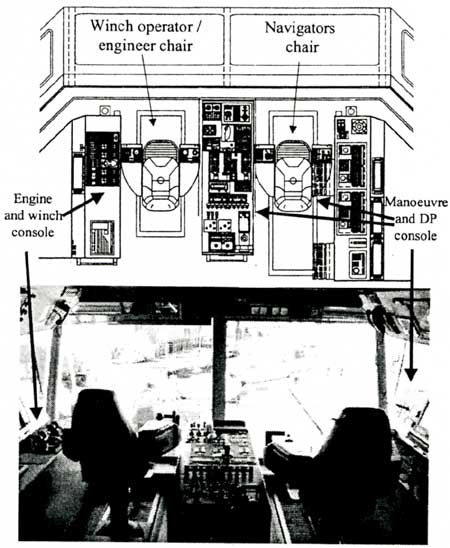
Since most new AH vessels is based on the well-proven UT-722 design it was natural for us to select this for our first approach. For the detailed layout we selected Far Scout as model (figs. 1 and 4). This ship was built at Aker Langsten Shipyard in 2002 for Farstad Shipping in Aalesund, with DnV classification: "DNV + 1A1, TUG/SUPPLY VESSEL, SF, E0, OIL REC, ICE C, DYNPOS AUTR, CLEAN, COMF-V(crn3). This decision was also based on part of a survey among 75 navigators [11]. The actual layout and class will not block us from later modifications to e.g. the Ulstein Design A-101. The simulator bridge will be arranged as a cockpit, identical to Far Scout (figs. 5 and 6).
Fig. 5 |
Instrument and operator arrangement from AH vessel Far Scout will be copied in the simulator. |
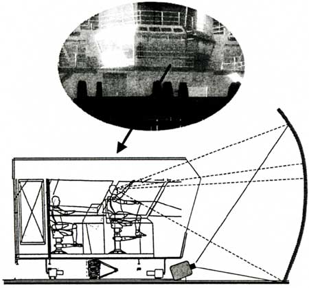
Based on our experience with the design of our HSC simulator the cockpit will be build as an stand-alone aluminium unit, fully prepared for implementation of a movable platform. Such solution also complies with the requirement of a large vertical field of view, which is essential when manoeuvring close to a rig.
3.1.2 Visual system
The visual simulation in this simulator deviate somewhat from conventional shiphandling simulators . In this simulator the operators need to have a large field of view (FOV) to be able to both view their own deck as well as up onto the rig, when manouvering close to this. These requirements led us to a solution with four vertically installed DLP video projectors with wide-angle lenses (fig. 6). DLP projectors are the most competitive when performance, maintenance and price are evaluated. Due to limited vertical space we will use a spherical projection screen. Geometrical and colour corrections, as well as edge blending, etc., will be taken care of. Image generators will be based on top of the line COTS PC technology, with a renewment frequency of less than two years. The first version will be based on 2.8 MHz Pentium4TM technology with GeForce-FXTM graphical generators. This solution gives a vertical FOV of 70°and a horizontal FOV of 120°. A 3D solution based on high frequency projectors and stereographic presentation will be evaluated at a later stage to improve perception and close range performance. Visual presentation of winches a deck details, as well as deck crew, will also be taken care of by a special designed monitor system, which is almost identical to what navigators have in real operations.
Fig. 6 |
Bridge cockpit with visual system, prepared for motion platform. |
3.1.3 Nautical instruments and integration
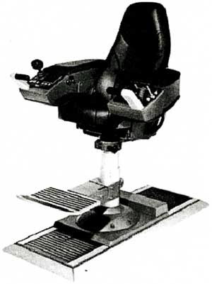
Since the simulator bridge is based on the Far Scout, most of the instruments and layout will be identical to the ship. In spite of this a survey was undertaken to document the relevance of the selected layout. The DP system will be based on the Kongsberg Simrad SDP-21, with integration of DGPS, HPR and FanBeam. This is the minimum requirement for class-2 DP-operations [12]. This comprehensive DP-solution will also improve the capacity and quality of the advanced DP courses, as well as give the possibility to give courses for reduction of the required demand for onboard practice. Joystick and all other manoeuvring levers will be delivered from RR as on the Far Scout. Other instruments of importance are the radar monitor from Furuno, the ECDIS from KMSS and the telemetric survey system displaying the anchor positions transmitted from the rig. All nautical instruments will be stimulated from the Polaris own-ship node, and controlled by the instructor. All nautical instruments and manoeuvring levers will be within reach from the sophisticated navigator chair (fig. 7).
3.1.4 Winch and engine instruments
Most of the large and modern AH vessels are equipped with hydraulic winch systems from Rolls-Royce Marine (RR), which is designed and produced in the Aalesund region. Therefore this winch system is also selected for the simulator. Since we will have as good flexibility as possible, two different configuration will be implemented (fig.8). The real RR winch computer will be stimulated from the Polaris instructor station, which will give the instructor an important role in the role-play during the AH scenarios. All winch controls and monitors will be within reach from the operator's sophisticated chair (fig. 7).
Fig. 7 |
The chairs will be fully instrumented to operate manoeuvring levers and winch control. |
Fig.8 |
The winch layout from Far Scout will be the main solution used in the simulator. |
3.1.5 Communication system.
To reproduce a realistic environment for AH scenarios the communication system is of vital importance. This system must simulate communication between the bridge and all possible units. This include rig, deck, intercom and shore based actors. This will partly be in accordance with GMDSS A3 [13].
3.1.6 Instructor and debriefing station.
The instructor station will be based on the well-proven Polaris concept from KMSS, with updated AH functionality. From this station most relevant factors can be manipulated:
・Other traffic and rig
・Environment (wind, current, waves, precipitation, visibility, light, etc.)
・Navigation instrument performance
・Communication
・Vessel performance (engine, winches, etc.)
・Anchor and anchor line functionality.
・Video and voice recording from the bridge.
Close related to the instructor station there will be space for comprehensive debriefing and additional personnel for advanced role-plays and communication. The importance of this is well documented from experience. The instructor station will be linked to the shiphandling and engine-room instructor via the installed gigaspeed network. This is important in the most comprehensive training scenarios and in R&D.
3.2 Modelling.
Realism is a key word in this type of simulators. It is therefore important that the simulator resembles real life as close as possible. This includes the mathematical and graphical models of ship and anchor system, as well as the bridge layout.
3.2.1 The vessel.
The mathematical model of the ship calculate the movement in 6 degree of freedom (DOF) based on the hydrodynamic forces affected by all kind of manoeuvring, anchor handling and meteorological conditions. Verification of the model is done by means of comparison to the manoeuvring test documentation of the real ship. These tests are done in various depths and under different weather conditions. The mathematical model used in the DP system onboard will be used in the simulator, as it is tuned and running onboard. This combination gives us confidence that the ship model will give the best possible validity, performance and realism.
3.2.2 Winch and anchor system.
Modelling of the winches and the anchor systems has two main tasks;
1. Stimulate the instruments and winch leavers on the bridge.
2. Contribute with correct and realistic forces to the mathematical model of the ship.
Initially two different hydraulic winch configurations will be designed. An additional configuration to the Far Scout is provided to include more flexible training to former and commonly used ships as well. Each winch model is based on a hydraulic motor, connected to the drum via a gearbox. The calculated pulling force takes into account the torque reduction due to increased drum radius, as the wire accumulates on the drum. This actual force (F) is given by the maximum force (Fm) and the ratio between the drum radius (R) and the radius with accumulated wire (Ra) :
F = Fm * R / Ra
Since the winch force can be reduced from e.g. 500 tons to 200 tons due to this, it is essential to introduce such scenarios to the trainees. The wire accumulation on each drum can be read from the RR winch instruments, as well as visually inspected on the emulated camera images (fig. 4).
The calculation of wire tension during chasing and anchor handling is based on non-linear equations, taken into account parameters like gravity, buoyancy, drag and bottom / chain interaction [14, 15, 16]. It is also important to implement forces due to pitch and roll of the ship in the actual wave condition, as well as safety factors and fatigue risk [17, 18].
3.2.3 Geographical databases and visual modelling.
In addition to the mathematical model it is important to have the best possible visual model to create realism in the scenarios. This includes modelling of rig, deck equipment, other AH-vessels and offshore structures that can be seen from the bridge. We have therefore made a lot of efforts to create some high fidelity models of rigs and field installations for AH-scenarios. In fig. 9, a model of the Frigg field in the North Sea is illustrated [19, 20]. For perfect integration with electronic charts and radar it is essential that the coordinates and datum parameters are correct. All geographical information is developed using 3D Studio Max and Multigen Creator TM and stored in Open Flight format.
The simulator bridge will be built on an aluminium deck and prepared for a motion platform. Until the motion platform is installed, the wave-induced motion will be taken care of by tilting the horizon. Based on experience from the shiphandling simulator at AUC, relatively slow motions give a very good visual effect.
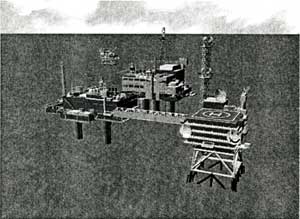
Fig. 9 |
The Frigg field in the North Sea is one of the areas where geographical models have been developed. |
Visual modelling of the deck equipment is important and have been emphasised by the experienced navigators during the planning process of the simulator. This includes winch drums, spooling devices, shark jaws, guide / towing pins, quarter pins, stern roller as well as chain and wire on deck. Some of the visual presentation is done by means of monitors on the bridge, others are observed through the bridge windows. Altering the ships heading can change wire angle from the guide pins. Based on environmental and operational factors the sound on the bridge will be simulated. Design of ship and deck equipment is modelled in 3D Studio Max and real time animation is done by software from Wild Tangent.
3.2.4 Instructor role and limitations
The benefits from a simulator depend not only on a realistic and high performance simulator. It is as important to have an experienced and enthusiastic instructor. The instructor will often have to fill the gap between the real world situation and what can be simulated. This gap can be considered as the simulator limitation. Absolutely realistic simulator based AH operations would be extremely difficult and expensive to develop. It is therefore a question what functionality that has to be taken care of by the instructor rather than the simulator itself. We have therefore decided that the following functions shall be taken care of by the instructor:
・Disconnection of shackles.
・Connect /confirm chaser or grapnel interaction with wire or chain.
・Confirm wire in shark jaw.
・Turning of anchors below stem roller.
・Braking of wire
・Introduce malfunction to winch, engine and navigation equipment.
・Introduce meteorological conditions to influence visual image, AH, and instrument performance.
・Take care of communication from rig, deck, engine, etc.
In each scenario there will normally be more than one instructor, dependant on complexity in scenario.
The mathematical model will normally have some deviations from the real world, but based on experience and preliminary tests we feel that the performance is well within acceptable limits for realistic training. The models will not be valid as tools for design calculations for mooring system and AH vessels.
|