|
STABILITY OF ARMOR UNITS
Damage location of armor units
To clarify the location of damage to armor units for a high mound, the relationship between wave steepness and damage location was examined by arranging armor units on a uniform slope of 1:3 slope. The wave steepness of experimental wave was 0.045 and 0.025, and the ratio of wave height to water depth was 0.3 and 0.5. In Figure 4, the horizontal axis represents x/L1/3, the ratio of slope length to wavelength. The slope length x is measured from the still water surface along the slope. The vertical axis represents the relative frequency distribution of the damage rate. The damage is concentrated just below the still water surface level. The peak damage location is constant with wave steepness and not with wave height.
In Figure 3, under the condition of h'/h
= 0.15, the damage is significant. This is because the shoulder of the slope is located at the damage
peak location on the mound slope.
Figure 4. Damage-prone area on
Comparison between wave-absorbing wall and vertical wall
Figure 5 shows the relationship between the ratio of mound depth to wave height h'/H1/3 and the stability number of armor units Ns. The dotted line represents the Ns values of the high mound composite seawall calculated according to Matsuda et al. (2000). It agrees well with the measurement results of our experiment on the vertical wall. The solid line represents the values calculated by our proposed method. When the coefficient of structural body shape CR is 0.4, it agrees well with experimental values.
Oblique incident waves
Figure 6 shows the relationship between the stability number Ns and the dimensionless berm width Bm/L1/3 for vertical seawalls and wave-absorbing seawalls, where the relative mound depth h'/h is set constant at 0.2 and the incident wave angle is alternated between 0°and 45°. The stability number is roughly the same when the incident wave angle β is 0°and 45°. The dotted line represents the values calculated using the proposed method. These correspond closely to agree well with the measured values.
Figure 5. Vertical wall and slit
Figure 6. Influence of incident angle
STABILITY OF THE FOOT PROTECTION BLOCKS
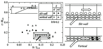
Figure 7 shows the relationship between dimensionless value of the thickness of foot protection blocks t/H1/3 and h/L1/3, where the relative mound depth h'/h is 0.2 and the incident wave angle β is 0°and 45 degrees. When β is 0°, noticeable differences in stability are not observed between slit wall and vertical wall because wave-breaking on the rubble mound exerts large affects. When β is 45°, the required thickness increases for the vertical wall type. When the mound is high and incident waves are oblique, flows above the foot protection blocks are generated in the normal direction of the structural body as shown in Figure 7. These flows cause the foot protection blocks to slide in the normal direction. Unlike for the vertical wall, the required thickness does not increase for the slit wall type, even when β is 45 degrees. This is because, under this condition, strong flows are generated inside the wave chamber.
| (Enlarge: 26KB) |
 |
Figure 7. Stability of foot protection blocks
CONCLUSION
The present paper can be summarized as in the following:
1) Stable mass of mound armor units decreases, when the upright section is wave-absorbing structure. However, when the h'/H1/3 is 0.4 or below, the difference between slit wall and vertical wall is small, due to the effects of wave-breaking on the rubble mound.
2) We proposed a calculation method for evaluation of the stable mass of armor units at a wave-absorbing high mound composite seawall, and it was validated by hydraulic model test.
3) For the vertical-type high mound composite seawall, the required thickness of foot protection block is greater in the case of β= 45°than in the case of β = 0°, because under oblique waves there are flows in the normal direction of the structural body. However, for the wave absorbing structure, the required thickness is not considerably greater in the case of oblique waves, because flow takes place only inside the wave chamber.
REFERENCES
Fujiike, T. K. Kimura, T. Hayashi and Y. Doi. 1999. Armor stability of rubble mound foundation for composite breakwater. Proceedings of Coastal Engineering (in Japanese), Vol.46:881-885.
Kimura, K., T. Hayakawa, S. Takahashi, K. Simosako and H. Oumeraci. 1999. Large scale experiment on wave overtopping of high mound composite seawall. Proceedings of Coastal Engineering (in Japanese), Vol.46:756-760.
Matsuda, S., K. Nishikiori, T. Matsumoto and M. Saitoh. 2000. Experimental study on the stability of armor blocks covering the rubble mound of composite breakwaters under impulsive wave action. Proceedings of Coastal Engineering (in Japanese), Vol.47:896-900.
Muttray, M H. Oumeraci. K. Simosako and S. Takahashi. 1998. Hydraulic performance of a high mound composite breakwater. International Conference on Coastal Engineering, Vol.26:2207-2220.
Schuttrumpf, H. Oumeraci, H. Moller, J. Kimura. K. and T. Hayakawa. 1999. Wave overtopping on a high mound composite type breakwater. Proceedings of coastal structures 99:397-404.
Takahashi, S. K. Kimura and K. Tanimoto. 1991. Stability of armor units of composite breakwater mound against oblique waves. Proceedings of Coastal Engineering (in Japanese), Vol. 33:596-600.
Takahashi, S. K. Tanimoto, K. Simosako and T. Hosoyamada. 1992. The proposal of impulsive wave pressure coefficient by the mound shape of composite breakwater. Proceedings of Coastal Engineering (in Japanese), Vol. 39:676-680.
Tanimoto, K. T. Tagyuu, T. Muranaga, K. Shibata and Y. Goda. 1982. Stability of armor units for foundation mounds of composite breakwaters by irregular wave tests. Report of the port and harbor research institute (in Japanese). Vol.21 No3:3-42.
|