|
Calculation method
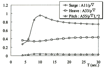
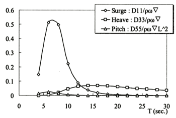
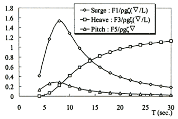
Added mass coefficients, damping coefficients and wave forces are calculated by making use of the singularity distribution method. This is a method of solving the integration equation that made the unknown the strength of the singular point. Using the Green's function, it distributes a source on the surface of floating unit in the singular point. In order to distribute a source, the mesh is constructed on the surface of floating unit. Added mass coefficients are shown Figure 3, damping coefficients are shown Figure 4 and wave exciting force coefficients are shown Figure 5.
Figure 3. Added mass coefficients
Figure 4. Damping coefficients
Figure 5. Wave exciting force coefficients
External force is taken as the amount of irregular change that changes with time history. It is assumed that motions of floating unit are small displacement. Therefore, a wind drag coefficient, a current force coefficient, etc. give a fixed value. The solution method of the equation of motion uses Runge-Kutta-Gill method.
Calculation conditions
In the present dynamic analysis in the time domain, in order to evaluate motion
when the maximum external force acts on floating unit, all external force shall be given in the same direction.
Therefore, in the present calculation, θwave, θwind and θcurrent are equals
to zero degree.
Wave exciting force
Exciting force is found using wave height. The time series of wave height are obtained by carrying out inverse Fourier transform about wave spectrum. In the present study, the modified Pierson-Moskowits type spectrum is used about a wave spectrum.
Wind force
Wind force is found using wind velocity. The time series of wind velocity are obtained by carrying out inverse Fourier transform about wind spectrum. The wind force coefficient is set up from the shape of floating unit on the water surface, and the time series of wind force is calculated based on an obtained time series of wind velocity. In the present study, the Hino type spectrum is used about a wind spectrum.
Current force
Current velocity is made into the fixed value, without changing with time history. Therefore, in motion calculation of this simulation, current force serves as a fixed value.
Drag force
In consideration of viscous influence, drag coefficient is found using Computational Fluid Dynamics.
Tension acting on mooring lines
Other, calculate about acting on mooring line of one point with hybrid mooring system of steel chains and wires.
Riser motion
The influence of mutual interference of the offshore floating unit and the riser is not taken into consideration. The forced oscillation was given as the maximum motions of the offshore floating unit on the top of the riser about the motion analysis of riser in the hang-off mode because the value of maximum motions is enough in a design stage.
Flow field around the floating unit
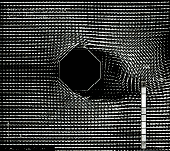
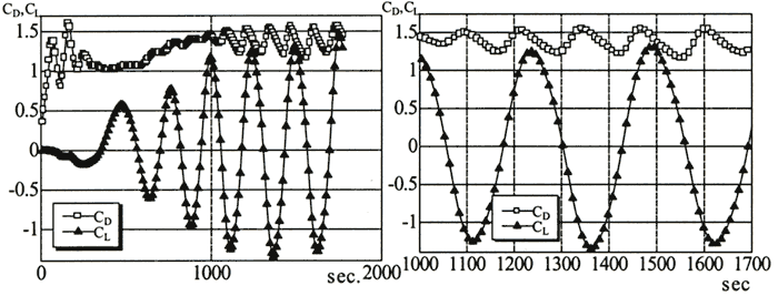
In order to consider motion of floating unit in the inside of the ocean, it is necessary to estimate the drag coefficient in consideration of viscous influence of octagon shapes. Here, the flow field visualization of the computational result using CFD (Computational Fluid Dynamics) is shown. Where, about computational conditions, the flow velocity is 0.5m/s. Reynolds number is 1.179 X 10⁷, Node number is 25904. In Figure 7, the Karman's vortex under the influence of viscous has occurred. If Karman's vortexes generate, the floating unit receives the force of a flow and the right-angled direction by turns. Then, if this frequency is in agreement with a natural frequency, a resonance phenomenon will be caused. This becomes easy to occur a noise and an oscillation of floating unit. As a result of calculation, Pressure distributions are shown in Figure 6 and Velocity vectors are shown in Figure 7. At T=1240s, time series of drag and lift coefficients are shown in Figure 8. Therefore, drag coefficient is 1.4.
 Figure 6. Pressure distributions
Figure 7. Velocity vectors
| (Enlarge: 25KB) |
 |
Figure 8. Time series of drag and lift coefficients, respectively (at T=1240s)
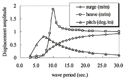
Characteristics of motion for only floating unit
Before considering the response of the floating unit system containing a mooring system, first of all, the characteristic of motion at the floating unit simple substance was examined. The response in regular waves without mooring lines (RAO) is shown in Figure 9. The horizontal axis expresses the wave period and the vertical axis expresses the amplitude of motion per wave amplitude of 1.0m.
Figure 9. Response in regular waves
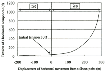
Mooring Characteristics
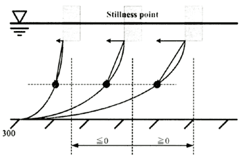
In the present, the mooring system is four points with Hybrid mooring system of steel chains and wires. The length of the mooring line is 2,550 m and the rapture load is 950tf. In order to calculate the response of the floating unit with mooring line, the mooring characteristic per a mooring (Fig.10). Figure 10 illustrates that the horizontal axis is the distance horizontal movement from stillness point and the vertical axis is the tension of a horizontal component. About centerline, the distance of horizontal movement from stillness point equals zero. Initial tension acting floating unit is 30tf. This state is that the Figure 11 illustrates (the stillness point).
When the distance horizontal movement from stillness point is greater than or equal to zero (the moving distance of floating unit increases gradually to positive direction), the horizontal tension will increase. According to Figure 11 this state is the right side of stillness point state. On the other hand, when the distance horizontal movement from stillness point is smaller than or equal to zero (when the moving distance of floating unit increases gradually to negative direction), the horizontal tension will decrease.
Figure 10. Characteristics of mooring line
Figure 11. Stillness point
|