OTC 13015
Repair of the Macaroni 10 x 6 in. Pipe-in-Pipe Flowline
Robert Gilchrist / Robert Gilchrist Engineering LLC (retired from Shell Oil Company)
Copyright 2001, Offshore Technology Conference
This paper was prepared for presentation at the 2001 Offshore Technology Conference held in Houston, Texas. 30 April-3 May 2001.
This paper was selected for presentation by the OTC Program Committee following review of information contained in an abstract submitted by the author(s). Contents of the paper, as presented, have not been reviewed by the Offshore Technology Conference and are subject to correction by the author(s). The material, as presented, does not necessarily reflect any position of try Offshore Technology Conference or its officers. Electronic reproduction, distribution, or storage of any part of this paper for commercial purposes without the written consent of the Offshore Technology Conference is prohibited. Permission to reproduce in print is restricted to an abstract of not more than 300 words; illustrations may not be copied. The abstract must contain conspicuous acknowledgment of where and by whom the paper was presented.
Abstract
The Macaroni Flowline system was the first J-lay installed pipe-in-pipe insulated flowline in the Gulf of Mexico. The flowline initiated at a subsea manifold in 3700 feet of water and terminated with a steel catenary riser (SCR) at the Auger Tension Leg Platform (TLP) in 2980 feet of water. To limit the consequence of loss of casing pipe integrity each flowline was divided into ten bulkhead-isolated compartments each some 6000-ft long. During construction of the second of two parallel flowlines the laybarge A&R cable failed with 3800-ft of pipe suspended in 3400-ft of water. The pipe fell to the seafloor. All of the pipe came to rest aft of the lay vessel in a pile of large loops. The barge was rigged to recover pipe alongside and away from the J-lay tower. The damaged section was severed using an ROV deployed shaped charge cutter and abrasive wheel. The end of the damaged line was recovered to the surface using a drop-on recovery clamp. The pipe was incrementally lifted and abrasive cut into 165-foot long lengths for onshore recycling. Upon removal of all damaged pipe the top of the suspended span was transferred to the J-lay tower pedestal and construction resumed.
INTRODUCTJON
The Macaroni flowline system was designed and installed with a view to providing an extremely reliable facility to transport produced fluids from a group of subsea wells in Garden Banks Block 602 to the Auger tension leg platform in Garden Banks Block 426. The subsea manifold and the Auger TLP are 62,000-ft apart. Unique features of the system are:
・ An insulated pipe-in-pipe system was installed for flow assurance. The insulation minimizes heat loss and maintains the flowing commodity stream above the hydrate formation temperature with some time allowance for shut-in.
・ Dual flowlines were installed to permit pigging and commodity displacement in the event of an extended shut-in.
・ Because the insulated annulus is at atmospheric pressure, the flowline pressure design could not take credit for external hydrostatic pressure like typical deepwater pipelines. The casing is designed for collapse.
・ Each insulated flowline was divided into ten compartments separated by steel bulkheads. This is was intended to limit the consequence of loss of casing integrity.
・ The flowline system was installed by J-lay to facilitate pipelay start-up (a connection sled was pulled in and pipelay initiated beneath an operating drill rig), minimize top tensions, minimize installation bending strain and facilitate SCR fabrication and hand-over to the Auger TLP.
The fabrication and construction of the system entailed numerous new activities:
・ Design of forged bulkheads.
・ Design of sliding pipe-in-pipe assembly method, including precise dimensioning to permit operation of automatic welding machines and automatic ultrasonic testing scanners.
・ Onshore insulation of double joints with polyurethane foam.
・ Onshore fabrication of pipe-in-pipe J-lay quad joints. The J-lay barge was designed for 165-ft long quad joints.
・ Upgrading of the J-lay system for pipe-in-pipe and an increased top tension design load of 775 kips for this and future projects.
・ Upgrade A&R capability to 490 kips.
・ Design of repair and recovery contingency equipment for pipe-in-pipe.
The last item above is an essential component of any pipeline construction plan. Repair of damage-to-the-work-in-progress is never a welcome activity, but a plan must be in place. In the case of deepwater flowlines and pipelines, job specific tools are usually needed due to the unique nature Of the facilities; and the high suspended span top tensions, particularly if the pipeline must be handled in a flooded condition.
At 2250 hours on 16-April-1999 the wisdom of contingency planning was made plain when the suspended flowline was dropped from the surface in 3400 feet of seawater (FSW). No personnel were injured, but a prompt and economical recovery was required.
DESCRIPTION OF THE PLPELINE
Pipe
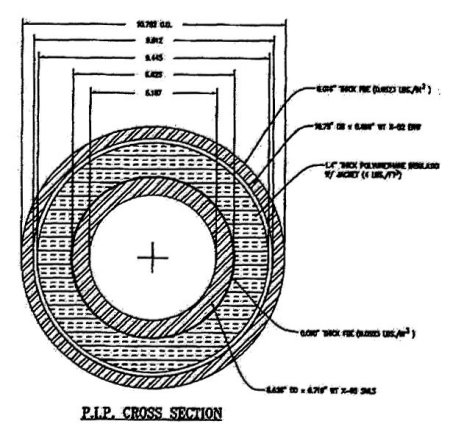
The inside conduit (referred to as the flowline) was a 6.625-in x 0.719-in wt API 5L X-65 seamless pipe. The outside conduit (referred to as the casing) was a 10.75-in x 0.469-in wt API 5L X-52 HF-ERW (high frequency electric resistance welded) pipe. The annulus was insulated with 1.4in of four pound per cubic foot polyurethane foam. See Figure 1. Cross Section of the Macaroni Pipe-in-Pipe Flowline.
Figure 1. Cross Section of the Macaroni Pipe-in-Pipe Flowline
Field assembly
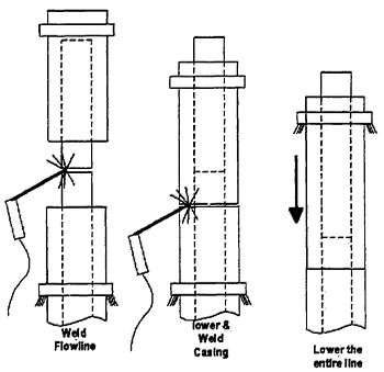
The pipeline was assembled using a sliding system with no metallic parts between the flowline and casing pipes. This was specified to maximize the overall efficiency of the insulated system. See Figure 2. Typical Quad Assembly Process
Figure 2. Typical Quad Assembly Process
Shear link
There was a structural linking of the inside and outside pipes, albeit not metallic. Before welding of the flowline commenced, approximately 3 gallons of two-part polyurethane polymer was poured into the annulus between the foam insulation and the outside pipe. There was a foam stop about 10-ft down the annulus to limit the annulus length to be filled. This material set up in a few minutes and locked the pipes so they would operate as a unit. The foam insulation remained intact; the only effect on the heat loss was replacement of about 10 feet of annulus free air space with solid plastic. See Figure 5. Shear Link.
Figure 5. Shear Link
Casing stretch
Note that before the polyurethane was poured, the weight of the entire suspended span was supported by the outside pipe and the inside pipe was only loaded with the self-weight of a single quad. To offset the stretch in the casing and keep the stick-up of the inside pipe consistent, the quads were fabricated with the inside pipe approximately 0.5-in longer than the outside pipe. Once in the field, on average every sixth pipe required a slight trim on the ready rack to the inside or outside pipe to bring the inside pipe stick-up back to tolerance.
Annulus compartments
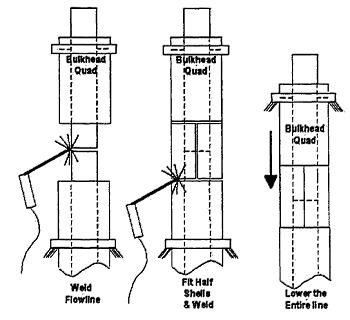
The shear strength of the foam and the Polyurethane annulus fill locked the pipes, but in no way inhibited flooding of the annulus if casing integrity was lost. The quads were 165 feet long and every 37th quad was a steel bulkhead quad that totally isolated adjacent annular compartments. This computes to a bulkhead interval of 6,105-ft. See Figure 3. Bulkhead Fitting. In this type of quad the casing could not slide down for girth welding. The casing was completed by welding in half shells after the flowline girth weld was complete. See Figure 4 Bulkhead Quad Assembly Process. The length of the compartments was established by cost optimization. The longer the compartments, the fewer the number of bulkhead quads required so the cost of bulkhead quad fabrication and installation went down with increasing length. On the other hand, the longer the compartments the longer the length of contingency pipe required to replace a compartment. The pipe order included enough pipe to replace a compartment. The break-even cost was a bulkhead every 37 quads considering out-of-pocket cost with no risk factoring.
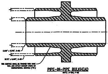
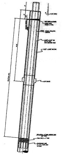
Figure 3. Bulkhead Fitting
Figure 4. Bulkhead Quad Assembly Process
ABANDONMENT AND RECOVERY SYSTEM
There were two pipe Abandonment and recovery systems on the barge.
Primary A&R
The primary system was a deck mounted traction winch and storage reel fitted with 4.25-in wire rope. The weight capacity of this system was 490 kips. This includes allowances for sheave friction. This was adequate for the 420 kip contingency weight of the suspended flowline in the flooded condition. This system was not routed through the J-lay tower due to tower strength constraints. A single wire run through a crown block has the effect of doubling the crown block load. So the main A&R wire was routed overboard at a point below the J-lay tower. For the 775 kip Jlay tower design case the pipe in the J-lay tower was handled by a single part sling rigged to the traveling block. At a point below the tower the pipe would be handed off to the A&R system for abandonment.
The only disadvantage of this system was the considerable time required to rig the pipe for abandonment and then hand it off to the main 4.25-in A&R system.
Secondary A&R
There was an alternative. The J-lay tower was fitted with a 2-7/8-in A&R system with a capacity of 300 kips. This had been adequate for earlier projects such as the Auger export pipelines. The Macaroni dry pipe suspended weight was 240 kips, so if a dry pipe was being handled the weight was within the limits of this alternate system. This was the preferred mode of handling given the savings in rigging time and the reduce personnel exposure to rigging activities.
Mechanical A&R Hook
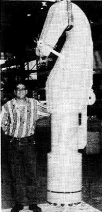
To connect the rigging to the pipeline the pipe was fitted with large hook secured to the pipe with a mechanical collet connector that gripped and sealed over the casing pipe. The mechanical system was selected over welding because the collet would leave the casing bevel ready for prompt resumption of pipelay. See Figure 6. Photo of Mechanical A&R Hook
Figure 6. Photo of Mechanical A&R Hook
CAUSE OF THE DROPPED PIPE
At the time of the incident the pipe was suspended with the top of pipe just below the keel of the barge. There had been a weather interruption that the barge was able to ride out by lowering the pipe below the stinger and weathervaning to reduce environmental forces on the beam. Steps were under way to recommence pipelay operations. The pipe was suspended on the 2-7/8-in A&R system and was being drawn up into the J-lay tower for resumption of pipelay. Suddenly the 2-7/8-in A&R cable parted high in the tower and the entire suspended span was lost.
Wire rope fatigue
Post incident analysis showed that the cable parted due to fatigue. The crown block was not a single large sheave but a series of 7 small sheaves arranged in an arc. This is referred to as a knuckle sheave. The cable had crossed the gang of small sheaves approximately 14 times during seven earlier A&R sequences. Unusual features of this cable break were that the independent wire rope core (IWRC) was broken at several locations and the outer cable strands had broken valley wires. This is in contrast to ordinary cable wear where the outer wires abrade and break.