SITUATION ASSESSMENT
ROV Inspection
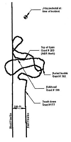
After the pipe was dropped a remote operated vehicle (ROV) was immediately deployed to assess the situation. Some four hours after the incident visibility was still substandard. The water was cloudy with fine grain sediments kicked up by a quarter million pounds of steel landing in a heap. As visibility cleared the pipe was followed and a map was generated. See Fig 8 Dropped Pipe Plan.
Figure 8. Dropped Pipe Plan
Map
There are several key components noted on the drawing:
・ Top of the pipe (quad #200). This was fitted with a collet locking A&R hook. See Figure 7 - A&R Hook. It weighed 5500-lb and was buried in the mud.
・ Buried buckle (quad #190). The pipe had buried itself deep under the mud. Ultimately it was discovered that this was the only location where the casing buckled and developed a through-wall break.
・ Bulkhead (quad #186). If casing integrity could be maintained from south of this point we could avoid having to replace pipe due to flooding all the way back to the next bulkhead quad(#149).
・ Bottom of the span (quad #176). This was the pipe that had to be brought to the surface with a dry annulus to continue pipelay.
・ The location of the J-lay pedestal at the time of the incident. Note that all pipe came to rest well aft of the vessel. In effect the pipe fell through the existing 'hole in the water'.
Flooded member detector
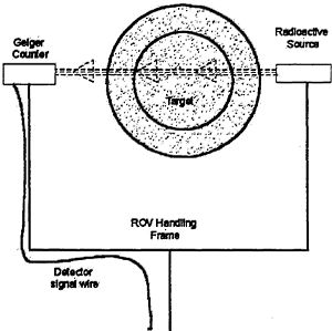
To assess the integrity of the pipe and casing an ROV deployed flooded member detector was deployed. This device has a small radioactive source and Geiger counter mounted on a fork. The counts are proportional to the average density of whatever is between the forks and thus interrupts the radioactive beam. See Figure 7. Flooded Member Detector. The detector was calibrated on the west flowline, which was believed to be dry. One loop of the dropped east flowline had crossed over the west flowline, but ROV inspection could not detect any damage.
Figure 7. Flooded Member Detector
The first survey with the flooded member detector was on 18-Apr-99. It found both the bore and annulus to be dry. There was a chance the hook could be snagged and the entire span lifted back to the surface!
Vessel Breakdown
Plans were progressing when on 20-Apr-99 the dynamically positioned lay vessel suffered a thruster failure. It would be 15 days before heavy lift field operations could resume.
ROV recovery preparations
During the time the lay vessel was down for repairs the ROV vessel dredged to uncover and inspect the dropped pipe. The flooded member detection survey was repeated with ambiguous results. The bulkhead was holding, from quad #186 back all readings showed the line was dry. All pipe from quad #177 to quad #186 was exposed and only exhibited smooth bends. From quad #186 to quad #200 the detector found sections with indications of flooded annulus, flooded annulus and flooded bore, and dry sections. It was hard to imagine that with over 1500-psi of hydrostatic pressure any defect would not quickly flood the pipe annulus.
RIGGING FOR RECOVERY
Connection to the pipe
There were two configurations for pipe capture.
The first was to capture the A&R hook that was fitted to the top of the span. For this a master link deployed on the 4.25-in A&R wire would be set in the hook by ROV and the span lifted. The hook was rated for 400-kips and had been proof tested to 600 kips.
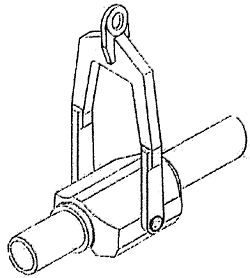
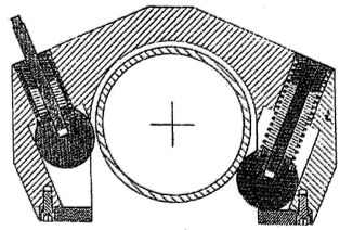
The second was a drop-on clamp that had been designed and fabricated as part of the project contingency activities. The clamp would be deployed on the 4.25-in A&R wire, dropped on the 10.75-in casing pipe with ROV assistance where it would be free to roll until it encountered a J-lay collar. With the J-lay collar bearing on the drop-on clamp the entire span could be lifted. The drop-on clamp was rated for 400 kips and had been proof tested to 600 kips. See Figure 9. Drop-on Clamp-Isometric and Figure 10. Drop on Clamp-Section
Figure 9. Drop-on Clamp-Isometrlc
Figure10. Drop on Clamp-Section
Lifting gear
The primary A&R had a capacity of 490 kips and was adequate for all recovery configurations. After lifting by A&R to a point just below the keel the suspended span could be handed to the J-lay tower A&R sling with a capacity of 775 kips or to the derrick auxiliary hoist, which had a capacity of 1100-kips.
Support foundation
Consideration was given to drawing the damaged line into the J-lay tower, but this was judged unacceptable because:
・ The recovered joints would be bent and the tower would only accommodate straight pipe. Damage to the J-lay tower would impede completion of the project.
・ The joints were to be cut remotely using high-pressure water entrained abrasive. Any scattering of abrasive could damage precision equipment in the J-lay tower.
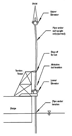
The J-lay tower was on the starboard side of the barge. For the recovery a short tower used for assembling TLP tendons was installed on the port side of the barge. See Figure 11. Hand-over-Hand Recovery Concept. The tendon tower frame had the following benefits:
・ The tendon tower was within the radius of the derrick auxiliary hoist.
・ The tower had a deck level foundation where the Jlay collars could be landed to carry the weight of the suspended span whilst the quad held by the derrick could be cut free.
・ The tower had an upper work platform where the suspended pipe could be dogged off for control upon severing from the pipe below.
・ The pipe to be cut off would be suspended in the open air and free to distort.
・ The remote abrasive cut would be made away from sensitive equipment.
Figure 11. Hand-over-Hand Recovery Concept
Elevators
The recovery would proceed with a hand-overhand methodology. The J-lay collar would not be set directly onto the tower foundation but would instead be landed in an elevator with a gate and two lifting pad eyes. After the upper pipe was cut and cleared the elevator would be rigged to the derrick for the next sequence. Two such elevators were used in rotation.
Pipe
underwater pipe cutting an ROV deployable two-stage shaped charge device had been developed ant tested as part of the project contingency engineering. The first stage was a charge consisting of two 10.75-in diameter girth cutters connected by two 12-in long longitudinal cutters. This charge would cut and separate the casing into two removable half shells. It was termed a 'window cutter'. The second stage was a 6.625-in girth weld cutter that would sever the flowline.
For surface cutting the equipment selected was a high-pressure water jet system with entrained garnet abrasive. The cutting jet was deployed on a remote controlled powered bug mounted on a band that circled the pipe. In one circular pass the abrasive water jet would cut the casing and flowline clean through with no hazard to personnel.
RECOVERY
Recovery of the first reach.
Recovery commenced on 4-May-99. The first recovery sequence was to deploy a 6-in master link on the A&R wire and acquire the A&R hook. There was some doubt about the integrity of the line, but all pipe had been inspected except for the buried section at quad #190. What was visible appeared to be fit for tension load.
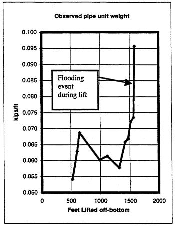
The hook was successfully captured with the master link and the lift commenced. The barge maneuvered with a view to maintain a smooth sag bend at the seafloor. A&R load was monitored. See Figure 12. Calculated unit weight during lift of the First Reach. All was well with more-or-less constant unit weight until the touchdown approached the buried buckle at quad #190. Here the load and calculated unit weight suddenly increased. The smooth sag bend became a dogleg and the pipe parted.
Figure 12. Calculated Unit Weight During Lift of the First Reach
I was decided to move the barge clear of the right-of-way and continue the recovery. This would leave a clean right-of-way and give the crew some lifting, cutting and stacking practice before attempting recovery of the critical reach from quad #186 back.
There was concern that the inside pipe might fall free from the vertically suspended 10 quads. However the buckle at the bottom was sufficiently bent to keep the inside pipe locked in place. The suspended pipe was transferred to the auxiliary hoist, the upper J-lay collar, directly under the A&R hook, was landed on the tendon tower foundation and the subsequent hand-over-hand recovery proceeded with no problem. Alter the first couple of quads the recovery time settled in at about 1.5 hours per quad.
Underwater pipe cut
While recovery of the first reach of 10 joints was underway the ROV commenced to cut the pipe just above the bulkhead at Quad #186. The first stage window cutter was deployed and fired. The cut was a bit ragged and it was only possible to remove one half shell. It would not be possible to fit the second stage girth weld cutter on the flowline.
With operations underway there was no time to make up another set of shape charge cutters. The ROV hydraulic powered grinder was deployed to cut the pipe with a pair of 14-in diameter by 1/8-in thick abrasive disks. The disks were sandwiched together on the tool arbor to enhance the durability of the abrasive wheel. It took several dives, but over the course of a night The ROV was able to at last complete the cut.
Clearing the Right-of-Way
With the first reach recovered and the pipe cut at quad 186 there was 500 foot long (three quads) loose section across the ROW. In this case there was no way to engage the top of the section and have the drop-on clamp yoke hinge over properly. In addition there was no way to keep the inside pipe from falling free during a recovery. Prudence required this section be pulled out of the way and abandoned. The drop-on clamp was used to latch on the section and it was dragged out of the way without the yoke hinging over. The latching balls were then retracted by the ROV to release the drop-on clamp. This also served as a practice run with the drop-on clamp and it worked perfectly.
Recovery of the second reach
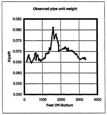
The barge shifted to a position over quad #186 and the drop-on was lowered and latched on the pipe. Again the barge was maneuvered whilst pipe was lifted to maintain a smooth sag bend. The A&R weight was monitored with a view to assessing casing integrity. The bore was 100% flooded and any sudden loss of casing integrity would show as a step change in A&R load. See Figure 13 Calculated Unit Weight During Lift of the Second Reach.
Figure 13. Calculated Unit Weight During Lift of the Second Reach
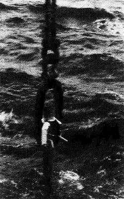
The top of the reach was successfully brought to the surface and transferred to the auxiliary hoist. See Figure 14. Drop on clamp at the Surface. Load = 310 kips. The clamp was landed on an elevator positioned on the foundation fork of the Tendon Frame. Pipe was cut back to quad #177. The last quad removed was curved with a straight tail, which indicated the entire damaged reach of had been removed. The A&R hook was used to transfer the pipe back to the J-lay tower.
Figure 14. Drop-on-clamp at the surface. Load = 310 kips
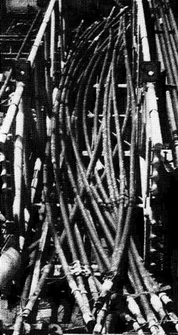
The pipe recovered was returned to shore and transferred to a scrap dealer for recycling. See Figure 15. Photo of Recovered Pipe
Figure 15. Photo of Recovered Pipe
Pipelay recommenced on 10 May and by 12-May the project was back to the progress milestone at which the incident occurred.
CONCLUSIONS
Project Planning
It is prudent to have a plan and equipment in place to affect a repair to the work in progress. The remote worksite requirements (far offshore and thousands of feet down) and the weight of suspended pipes in deepwater call for unique tools that take time to design and fabricate. Items to acquire are:
・ Pipe cutting equipment.
・ Pipe capture and lifting equipment such as the drop-on clamp.
・ Hoisting equipment capable of lifting the line in the flooded condition (or a dewater plan and equipment that will permit a void lift).
Tools acquired for construction contingencies can also be important in effecting repairs during the operating life of the pipeline.
Pipe Design
The dropped pipe incorporated a buckle in the 10.75-in x 0.469-in wt X-52 casing that would have progressed as a running buckle if the casing was a plain pipe. The very stout internal flowline prevented the casing from assuming the classic 'dog bone' cross-section shape and a running buckle did not occur.
Dropped Object Planning
In the case of the dropped Macaroni pipe and earlier event at Mensa the pipe landed aft of the lay vessel. This was with near-vertical pipe top angle; the Macaroni line was installed with a tower angle of just 5 degrees incline from vertical. It follows that lay vessels can safely approach and transfer steel catenary risers to facilities located above critical installations.
The Macaroni parallel flowlines were separated by 200-ft. One loop of the dropped pipe actually fell across the previously installed line. No damage was incurred, but if the incident had occurred with the West line the loop would have fallen over the electro hydraulic umbilical and not a pipe. Separation by 1/10 of the water depth would have eliminated contact with the companion flowline.
Safety
This was the third severed A&R cable event for the work group in as many years. That was the common thread. Otherwise there were different contractors, different types of vessels, and different operational phases. It is extremely important to review every detail of all rigging and load bearing structures. Personnel must be kept well clear of these operations unless they have essential duties that are part of the A&R operation.
Cost
The economic cost of dropped pipe incident amounted to approximately 10% of the Macaroni project flowline costs. Due to the advance design and procurement of key repair components and pipe materials there was no schedule time lost apart from the actual repair operations. Twenty-three quads(3,800-ft of pipe) had to be replaced.
ACKNOWLEDGMENTS
Responding to the dropped pipe incident required untold amounts of creative work and creative arrangements by a host of supporting entities. Suppliers, contractors (including competitors), vessel operators, service companies, Federal authorities and Shell's management all pitched in to help get this project back on track from what first appeared to be an almost impossible situation.