The monitoring system and test ships
(1) Outline of monitoring system
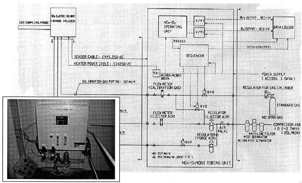
5 The monitoring system is divided into three blocks, sensor block, control block and data recording block.
Sensor will be fixed to the exhaust pipe. The control unit will be arranged somewhere in the engine room considering ease off access to the unit. The data recorder should be situated in the engine control room. Fig 3 shows the whole system and a photo of the control unit installed in the engine room of the test ship.
(拡大画面: 201 KB)
Fig.3 The monitoring system diagram and a photo of a control unit on-board
(2) Test ships
6 Following three ships have been selected to the field test:
Table 3 List of test ships
| |
Ship-
owner |
Name of vessel |
Type of vessel |
Type of main engine |
Output x Engine speed |
| 1 |
MOL |
Ikomasan |
VLCC |
Mitsui-MAN-B&W 8S80MC |
34,100 PSx68 rpm |
| 2 |
NYK |
NYK Antares |
Container |
DU-Sulzer 1 1RTA96C |
72,467 PSx94 rpm |
| 3 |
K line |
Mediterranean
Highway |
PCC |
Kobe-Diesel
-Mitsubishi
8UEC60LSII |
8,953 PSx99 rpm |
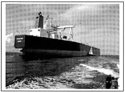
Fig.4 "Ikomasan"
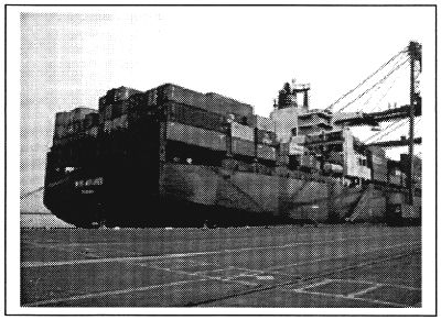
Fig.5 "NYK Antares"
(3) Outline of constant volume combustion chamber test rig
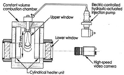
7 When using different types of fuel, samples are taken from engine inlet and analyzed by DNVPS. Items for analysis are conventional items plus nitrogen content. The NOx generation from these samples is also measured using the constant volume combustion chamber test rig, and the NOx values are compared with monitoring records on-board. If we find good agreement or relation between NOx monitoring records and test rig NOx figures, we are intending to conduct combustion tests using wider span of nitrogen distribution with artificially blended fuel, by this simple test rig to determine the conversion rate of fuel bound nitrogen to NOx.
8 Furthermore, if necessary, we would like to make a confirmation test of the conversion rate of nitrogen in fuel by using single cylinder two stroke cycle 400mm bore slow speed test engine. In this case, the NOx will be measured using two analyzers, CLD and zirconia.
Fig. 6 The constant volume combustion chamber test rig for NOx measurement