|
4.4 The relationship with path-prediction
For the relationship with path-prediction see figure 5. The section contained in the inner rectangle in the figure belongs to the subject of 'mathematical ship models' and, did not belong in the research concerned.
Fig.5 Path prediction modeling.
The issue of how much rudder and revolutions are needed to achieve a given result is something pilots and navigation officers will have to resolve. This is certainly the case when considering a ship's behavior in shallow water, which is a problem yet to be fully solved. What this paper is about, however, is that section shown within the bold rectangle in figure 5, namely, what the ship has to do (speed and rate of turn) to follow a given (curved) track.
4.5 Examples
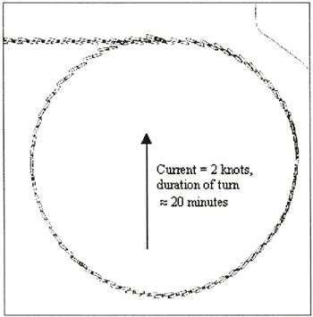
Example 1; Calculations were made for a turning circle (a real-time simulator run) in a homogeneous current field of 2 [knots] with HNLMS Zuiderkruis. The speed through the water was kept at exactly 8 [knots]. With the help of a printed table of heading (100 interval) and corresponding rate of turn the latter was kept exactly to the values shown by the table. During the run, which took about 20 minutes, all navigation equipment like radar and GPS was switched off. The only equipment used was the rate of turn indicator. The planned radius of the turn was 900 [ml. The radius of the simulator run appeared to be 4% more than planned. The position at completion of the turn was nearly the same as where the turn was initiated. The result is shown in figure 6.
Fig.6 |
Plot of a real time simulator run with HNLMS Zuiderkruis, using the preliminary version of the computer program. |

Example 2; A logical consequence of the application in a homogeneous current field is the search for a method whereby the current is partially navigated. Such is the case when entering a harbor from a river flow: as soon as you leave the river the current reduces. In order to simulate this sequence of events bespoke software has been written. In this simulation discontinuity in the current picture is, as yet, still assumed: ie. the abrupt (therefore not gently along a gradient) lessening of the current. These situations occur in practice: the so called, current rip or tide rip. After starting the program it is necessary, as in the previously described simulation at sea, to input various data. An important extra detail is that an acceptable remainder from the change of heading must be determined which, once in the harbor entrance, can still be completed. This is of course dependent on the turning ability of the ship and the width of the harbor basin. Figure 7 shows the plot from a run where the Waalhaven in Rotterdam is entered by a container vessel (length over all 300 [m]). The tidal stream on the river runs from West to East. The ship has to turn from an easterly course to starboard to enter the harbor. The thin line represents the limit of the tidal stream. In the harbor basin to the South of this line there is therefore no current. Given that an attempt is made to follow a circular arc for the part of the turn in the river, the ship has a particular angle of approach for passing the tide rip. From that position and the relevant course, after a kink in the track, the ship follows an earth stabilized circular arc once more until the final heading is reached. The program recommends a position for initializing the maneuver (including correcting for time and distance necessary for building up the required rate of turn). Certain approaches to this already exist and have been used for a long time. The main aim of the program is to show the effect of the current, the consequences of the approach used, to recommend the position to initialize the maneuver and to show the rate of turn needed. The latter is interesting in terms of passage planning. The question is, is the maximum needed value of rate of turn feasible for a specific ship? Note for figure 7: the line between the western and eastern side of the harbor entrance is the tide rip, the thick line (track 1570) shows the desired track inside the harbor.
Fig.7 |
Plot from a simulation entering a harbor from a river. |
Investigations regarding RoT planning in a non homogeneous current field (non homogeneous with respect to velocity and direction) were started but have not yet come to an end.
4.6 The use in daily practice
Apart from numerical values in a table (heading, RoT etc.) that can be used in daily practice, the possibility to run a fast-time simulation will also be implemented in the module of 'Pilot guide'. This may be very useful for passage planning and master-pilot exchange. Figure 7 is a screen dump of a fast-time simulation in Matlab. This is a preliminary version since the screen lay-out is not yet standardized (like the module for wind loads). In the future we hope to be able to present the fast-time simulations as an extra layer on the electronic chart of the portable pilot unit (PPU).
|