|
NEW TECHNOLOGY ON MARINE SIMULATORS
Knud Benedict
(Hochschule Wismar, University of Technology, Business and Design, Dept, of Maritime Studies Warnemünde, R. - Wagner - Str. 31, 18109 Rostock, Germany; benedict@sf.hs-wismar.de)
Abstract: The development of technology in marine simulation is a steady process driven by new inventions and by user needs. Simulator technology is based on the latest development of IT technology, it is an extremely wide spread field, under hard competitive pressure. This paper focuses on bridge simulators and discusses some selected elements in detail, where others fields can only be strived. To make the development transparent some examples are given of elements of simulator technologies used in the MSCW over the years.
Furthermore, it is concentrated on the "Simulator User point of view" onto simulation technology instead of describing technical features in detail, i.e. what is useful and applicable at the current state, along with some views on later developments.
1 INTRODUCTION
The development of technology is a steady process driven by new inventions and by user needs. Marine simulators have made progress constantly since when they have emerged and stated to be used for training in the years around 1970-80.
Now the field of simulator technology used is based on the latest development of IT technology. It is an extremely wide spread field and lies under hard competitive pressure with the following tendency:
By improving IT Technology it is now possible
- To incorporate very complex functions and operations on small but powerful PCs instead of requiring large computer cabinets as before.
- To use capabilities of networking of separate Part Task and even Full Mission simulators to complex simulation facilities, covering more and wider training areas than ever before.
The content of this paper will be somehow limited: It focuses on some selected elements in detail whereas others can only be strived (or not even be mentioned). The emphasis will be put onto the following aspects:
- Bridge and navigation simulators with the details of visualisation and elements of instructor control
- Simulation of sensors on board, ECDIS and new ship-born equipment, modelling of ships and environment conditions,
- Interfacing of simulators to complex simulation systems
- CBT-Training / Instructorless training on various areas as preparatory measures for full mission training
Another reason for limitations could be the lack of access to information because some manufacturers have not disclosed their latest state fully. This paper can only rely on the information which was made available to the author.
Furthermore this paper concentrates on the "Simulator User point of view" onto simulation technology instead of describing technical features in close detail, i.e. what is useful and applicable at the current state, along with some views on later developments.
2 BRIDGE SIMULATORS
2.1 General
For this type of simulators both the full mission technology has improved and smaller systems as desk top version have made a big step forward.
For larger systems the visual system plays a vital role, therefore it will be dealt with in the first place. It is followed by so called virtual reality systems which can be seen as an alternative emerging technology.
Some specific features for on board equipment have arrived on ships over the last years which now have to be necessarily implemented as new technology in the simulator world. Examples for these elements are new sensors, ECDIS systems, fitted now with Automatic Identification Systems (AIS), and some Expert-/advisory systems for ship operation support.
Nevertheless there were some developments in propulsion and steering systems of ships like e.g. Azimuth propeller, which requires some new elements in steering controls on the simulator bridges and some efforts in modelling of ships dynamic. Along with the possible Environmental elements heavy seas and 3-D-waves in the visual systems there are also some efforts to be made for modelling these environmental issues for the ship models.
2.2 Visual Display-Systems development
2.2.1 Image Generation and General Systems Aspects
In former days real-time image generating hardware was expensive and proprietary. Today the use of COTS components in terms of hardware and software is possible. The selection of the visual system hardware (pc components) depends on the required performance, especially image resolution, database complexity and quantity of dynamic objects as well as special features like lights or mirror effects. There are a lot of different interfaces used by the visual system ([3] ):
Important is the use of standard interfaces. Typical hardware interfaces are the physical network and the connection to the display system. For network usually Ethernet (100MBit or Gigabit) and partly fire-wire is used.
The popular logical data base format is the Open Flight format. This format is a well-known standard industry format and will be supported as an output format by nearly all data base generation or modelling software. A more complex data base format is SEDRIS.
Internally the image generation software has a standard interface to the graphic driver / graphic hardware . Actually there are two standards : Microsoft Direct3D (part of Microsoft DirectX) and OpenGL.
One key feature of an image generation system is the levels of configurations and enhancements. Typical configuration levels are the video resolution, field-of-view of the channel(s). Enhancements can be the possibility to add channels easily or put new features into the whole system.
The system-delay time should be less 100 msec for own and target motions is necessary to get a smooth impression (man-in-the-loop). In a multi channel system the synchrony of the data and the display is necessary to get a smooth image without visual artefacts like broken lines between two adjacent channels.
The major task of visual systems is to generate a training relevant image of the scenario. To increase realism and acceptance in a ship handling simulator, it is important to simulate basic nautical features. First the system has to handle light points with time (flash codes) and geometric parameters (e.g. sector visibility). More sophisticated features are 3D-waves and fluids (like oil spill) or ice on the water surface.
Normally a visual system is a subsystem of the simulator. The visual system has to be easily integrated into the simulator / simulator network, To fulfil this, the use of a standard network interface in terms of software (e.g, UDP) and hardware is helpful. For communication between the simulator and the visual subsystem the interface design document contains all logical information.
The MTBF of the visual system and the maintenance rate is a key feature: The availability shall be greater than 95%.
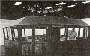
Figure 1 : |
Example of visual system for bridge simulator (BSS Royal Malaysian Navy) |
2.2.2 Display System aspects
Today there three major types of projector systems available: CRT, LCD and DLP projectors:
At a CRT projector (Cathode Ray Tube) an electron beam is sequentially writing the image on a phosphor layer where the electron beam is continuously deflected. Therefore any line shape can be written. This is an important feature for the projection on a curved screen. Also different image sizes and resolutions can be shown by one and the same CRT-projector.
To get a coloured image three tubes in the primary colours red, green and blue are needed. Then the three images had to be overlaid on the screen to form a coloured image.
For the LCD projectors (Liquid Crystal Display) there are two different technologies today.:
- The transmissive LCD is working like the principle of the classic slide projector. The LCD-panel composed of a matrix of pixels is illuminated by a lamp. Depending on the voltage applied on each pixel more or less light is passing the LCD-assembly. To get a coloured image we need again three LCD panels for the red, green and blue part of the image. Only one lens is needed - versus three at the CRT projector - to throw the image on the screen.
- The reflective LCD (LCOS: liquid crystal on silicon or JVC's D-ILA) is illuminated from the front through a polarising beam splitter.
Both types of LCD projectors have a fixed matrix structure for the pixels. We have discrete pixels which cannot change shape. The image source has to have the same resolution as the LCD panel to get the optimum quality.
A DLP projector (Digital Light Processing) has also a fixed matrix structure generated in a silicon wafer. Each pixel is represented by a small mirror. Each mirror has two states. At one state the light of the lamp is reflected through the lens to the screen and in the other it is absorbed by a baffle in the projector. To get a grey scale the time for the on state is varied. To get colours we need either three DLP chips - like the LCD - or we use just one DLP chip with a colour wheel in front of it. In a one chip projector the three images (red, green, blue) are shown sequentially.
There are two ways data transmission to the projector: analogue or digital.
The analogue interface has three wires for the red, green and blue channel (RGB. Important for the transmission and the image quality is the quality of the cable. For high resolution (number of pixels) and increasing frame rate it needs more bandwidth. For digital transmission the DVI interface is specified. For the DVI there are some restrictions. For longer transmission lines than 5 m we need a repeater or an optical transmission. The other restriction is in the pixel clock.
There are four parameters specifying a display in simulation: brightness, contrast, Field of View (FOV) and resolution. Unfortunately these parameters are not independent of each other.
This means for example when the FOV is increasing the contrast is decreasing because the stray light level is increasing due to multiple reflections of light. The resolution is a complex parameter which is dependent from the IG, the projector and the projection geometry. The more distortion correction you need the more the resolution is decreasing.
Distortion correction is an important issue for instance if the projectors are mounted above the ship bridge. The result is a trapezium distortion; using a curved screen we have also a bow and a non-linearity in the image. All the corrections electronically have to be made. This process needs time (latency) and reduces the resolution.
In multi-channel arrangement for the projectors the single channels have to be blended to form a homogenous panoramic image. This is done by the edge blending unit which can be inside the projector or as an external unit between IG and projector.
The throw distance of the projector is given by the used lens. With digital projectors (LCD; DLP) we have only one lens compared to three lenses for CRT projectors. Using one lens it is possible to introduce an optic with variable focal length. Such a zoom lens makes it easier to place the projector. Today there is a big range of lenses on the market to cover anything from wide angle to telephoto with fixed and variable focal lengths.
For many simulation applications the visualisation of light points is an essential requirement. Light points have to display without flickering effects and with constant brightness when the point moves across the screens in a large projection theatre.
For simulation it is important to have an excellent image at all times of the day - from midnight to noon.
- LCD and DLP projectors have excellent capabilities (brightness, contrast) for daytime visualisation; however, up to now they have difficulties for dark images as they are necessary for night scenery. A normal projector cannot show real-black but only a dark grey.
There are options either to dim the light output depending of the time of day or to flip a neutral density filter in front of any projector prior to a night simulation.
- CRT projectors are not that bright, but do not have these problems with night time simulation as they can project real-black.
The initial set up and final alignment of the projection theatre always takes some time. First the projectors have mechanically to be aligned as good as possible. Then the distortion correction has to be performed. This can be made automatically by some systems to quite a good level.
The alignment of the edge blending and the colours of the different channels have to be carefully adjusted. There are research activities to align the edge blending also automatically by a digital camera and software optimising the blend parameters.
Using digital projectors the job is normally done after the initial alignment. There are no or only minor changes over the life time of the lamp inside the projectors. But if one lamp has to be exchanged it is nearly impossible to align the projector with the new lamp to the other ones. Therefore all lamps have to be replaced simultaneously.
The situation is different with CRT projectors. A regular realignment has to be made on a daily or weekly basis. But modern CRT projectors have an auto-alignment system. It performs the alignment within less than one minute. The MTBF of modern projectors is typical more than 10.000 hours. The lamps have to be replaced after 1 500 to 2000 operating hours. New lamp designs give longer life times.
2 2.3 Virtual Reality VR
For virtual reality displays there are two major devices: Head or Helmet Mounted Displays (HMD) and caves.
- A cave is a big cube with up to 6 rear projection screens where the trainee is inside the cube (cave). He is wearing glasses to get a stereo image from the virtual environment he is exploring. In a cave more than one person can watch the images on the wall. Due to the great complexity of the big stereo images on 3 to 6 walls a cave is a pretty expensive display.
- A HMD is for just one person. He has a limited FOV, varying form 30° circular to 120°x 50°. There are stereo devices as well as monocular ones. For the display CRT's are used as well as LCD's. For the HMD you need also a head tracker. It is measuring the position and orientation of the head.
A big advantage of a HMD to the cave is that you need only one or two (stereo) IG channels. This and the reduced FOV makes a HMD much cheaper than a cave.
For nautical simulation you would need a coloured HMD with a high resolution (XGA or SXGA). The FOV should be greater than 40°. A stereo image is not needed. A look-through device should be chosen so that the trainee can see and handle the instruments of the ship bridge.
As Input-Devices mostly Headtrackers and for specific purposes keypad or a mouse are used. For better orientation in space a space mouse with movement in three axes is a good choice. Up to now the use of data-gloves as an input device hasn't a big acceptance.
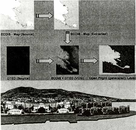
2.2.4 Modelling visual sceneries from Electronic Charts - Visual Coastline Generator
In important aspect in generation of visual sceneries is a cost effective generation process. So higher the capacity of the visual system are so more detailed the sceneries can be - and so more workload and costs occur. By means of semi-automatic processing tools the generation process can be speeded up, there are benefits like reduced costs, increase of quality and database density.
This will be achieved by:
- Use of public available data ECDIS S-57 / DTED as source map
- Automatic generation of 3D-terrain
- Automatic inclusion of nautical feature-models
- Automatic texturing
- Optimization of 3D-terrain database
Figure 2: |
Visual Coastline Generator: Process of Semi-Automatic modelling of visual sceneries from Electronic Charts to final Open Flight Data base |
|