|
A PARAMETRIC STUDY OF POWER PLANT PERFORMANCE USING DEEP-SEA WATER FOR STEAM CONDENSATION
M. Kadoyu, Y. Eguchi and F. Takeda
Central Research Institute of Electric Power Industry
Chiba, JAPAN
kadoyu@criepi.denken.or.jp
ABSTRACT
Power plant performance is parametrically evaluated in applying deep-sea water to a steam condenser as a heat sink. A 600 MWe fossil thermal plant is selected as a benchmark plant for the evaluation, and plant performance and hardware requirements are calculated under various conditions using a heat balance analysis code. The results show that, for an existing power plant designed for surface seawater, power generation can be improved by at most 3.5% in northern and central Japan in summer by applying deep-sea water. Moreover, the heat transfer area requirement of a steam condenser can be considerably reduced with the use of deep-sea water for optimally designed power plants, together with some improvement in plant efficiency.
INTRODUCTION
In steam power plants, power is generated by turbine rotation driven by the
pressure difference between a boiler (turbine inlet) and a condenser (turbine outlet). Since the performance
of a condenser has a direct impact on plant efficiency (or heat rate), intensive studies have been conducted
on its improvement ( Cooper, 1996; Tsou, 1991). Use of deep-sea water as a
heat sink of the condenser would have a beneficial effect on plant efficiency, because (a) a high vacuum
is realized in a condenser due to the coldness of the deep-sea water, (b) the inefficient off-design operation
of a condenser can be avoided due to the dramatic reduction in seasonal temperature variations, and (c)
the purity of deep-sea water prevents the pipeline from biologically fouling, thus saving on maintenance
costs. If these positive effects pay for both the initial investment required for pipeline installation
for deep-sea water and the additional running costs for pumping water up from the deep sea, the use of
deep-sea water seems a promising option as a method of plant efficiency improvement.
In the present study, the authors have evaluated power plant performance with a numerical model, assuming the use of deep-sea water to condense the exhaust steam. A 600 MWe fossil thermal plant is selected as a benchmark plant for the evaluation. That evaluation was performed for an existing plant and a newly designed one, where hardware specifications are fixed in the former, but changeable in the latter. For an existing plant, whose hardware was originally designed for surface seawater cooling, plant performance is calculated using a heat balance analysis code, assuming deep-sea water-cooling. For a new plant designed for deep-sea water-cooling, the hardware requirements of a condenser and a seawater pump as well as plant performance are similarly calculated.
In what follows, the evaluation method is explained first. Then numerical results are presented, including the seasonal performance of a conventional plant, that of an existing plant with deep-sea water application, and the hardware specifications and performance of a newly designed plant. Finally, some concluding remarks are made.
EVALUATION METHOD
Plant Model
A 600 MWe fossil thermal plant is selected as a reference plant for the evaluation.
The numerical model was constructed using the commercial plant analysis codes, STEAM-Pro and STEAM-Master
( Thermoflow. Inc., 1997). The former code allows us to create a numerical
model of a plant based upon the user input data of each primary component, and to estimate plant performance
under the design condition. The latter code permits us to compute the plant performance under off-design
conditions.
Though all the plant component models are well described in the manual, the condenser model merits a more detailed explanation here since the heat transfer character of the condenser is important in evaluating plant performance in the present analysis. The overall heat transfer coefficient of the condenser is computed by the reciprocal of the sum of four thermal resistances, i,e., the internal water convection, tube wall conduction, fouling, and the external condensation. The heat transfer of internal waterside convection is computed by the Dittus-Boelter correlation:
Nu=0.023Re0.8Pr0.4 (1)
where Nu is the Nusselt number, Re the Reynolds number, and Pr the Prandtl number. The tube wall thermal resistance, Rtube, is given by the theoretical formula as,
Rtube=(d0/2K)In(d0/di)
(2)
where do and di are the outer and inner tube diameters, while K denotes the thermal conductivity of the tube material. The condenser fouling coefficient is specified by the user. The heat transfer due to external condensation, hsteam, is modeled by the scaled Nusselt correlation, which was originally derived for static laminar condensation:
hsteam=0.728C(gρ2κ2H/μd0ΔT)0.25 (3)
where C: correction factor, g: gravitational constant, ρ: water
density, κ: water thermal conductivity, H: latent heat of condensation, μ: water viscosity, Δ T:
condensation temperature difference. The correction factor is introduced to take the effects of turbulent
vapor shear into account, and is usually set between 1 and 1.5. Though the Fujii's correlation ( Fujii,
1979) includes the effect of vapor flow, the scale Nusselt correlation is used in the code because
the velocity profile in a condenser is unknown.
Environmental and Operational Conditions
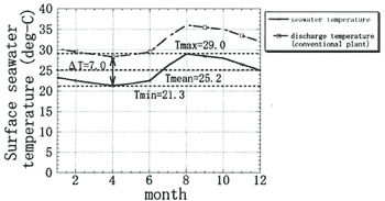
The temperatures of deep-sea water and surface seawater also vary from site to site. Therefore, in the present calculation, three sites (Site-N, Site-C and Site-S) are selected from northern, central and southern Japan, where the deep-sea water temperatures are assumed to be 3℃, 5℃ and 9℃, respectively. The seasonal variations in the surface seawater at the sites are shown in Figures 1(a), (b) and (c) with the discharged seawater temperatures in a conventional plant which vary in accordance with the seawater temperature, since the temperature rise in a condenser is usually kept constant (7℃) in Japan.
The performance of an existing plant was evaluated under constant heat input conditions for each site. On the other hand, the performance of a newly designed plant was estimated under constant electricity output conditions. The hardware requirements were also examined for a seawater circulation pump and a condenser in the newly designed plant.
(a) Site-N
(b) Site-C
(c) Site-S
| (Enlarge: 32KB) |
 |
Figure 1. Seasonal temperature variation of surface seawater
|