|
MOTION ANALYSIS OF OFFSHORE FLOATING UNIT FOR 1MW CLASS OTEC PLANT
Hideyuki Niizato1, Shin Okamura2, Sadayuki Jitsuhara3 and Yasuyuki Ikegami4
1Hitachi Zosen Corporation
Osaka, JAPAN
niizato@hitachizosen.co.jp
2Universal Shipbuilding Corporation, Tokyo, JAPAN
3Xenesys Inc., Tokyo, JAPAN
4Institute of Ocean Energy, Saga University, Saga, JAPAN
ABSTRACT
In this paper, the offshore floating unit for 1MW class OTEC (Ocean Thermal Energy Conversion) plant that can be stably and safely in severe environmental conditions is proposed. The proposed offshore floating unit has octagon column shape of 24 m diameter and 29 m height, and is moored by four points with hybrid mooring system of steel chains and wires. A flexible riser pipe of 700 m long is equipped at the bottom of platform. In order to confirm whether it is safe, nonlinear hull/mooring coupled dynamic analysis of the designed offshore floating unit is carried out in the time domain and it is evaluated the characteristics of motion in severe environmental condition like a typhoon. Environmental condition was decided in consideration of the return period of 100-year storm based on the observed data over the long period of time of ocean space. In the dynamic analysis, first of all, hydrodynamic coefficients are calculated by using the singularity distribution method (References). In considering viscous influence, drag coefficient is calculated by using CFD (Computational Fluid Dynamics). Since the mooring force has strong nonlinear characteristics, the equations of motion are solved in the time domain by means of the Lunge-Kutta-Gill method. Dynamic analysis of the designed riser pipe is carried out, too. As a result of calculation, the motions of an offshore floating unit for OTEC plant were very small. The present designed offshore floating unit for OTEC plant will be brought to realization.
INTRODUCTION
In offshore activities, examples of the hanging-off riser pipes are numerous
such as a pipe for ocean thermal energy conversion. The motions of an offshore floating unit for OTEC
plant with the flexible hanging-off riser pipes are very complex dynamic behavior. Many researchers have
investigated the offshore floating structure with flexible riser. Allan T. Maris et al (1980) discussed
the analysis and design of the Cold-Water Pipe for the OTEC-1MW power plant system. H. Maeda et al (1991)
investigated into the dynamic behaviors of a deep water utilization system composed of a two-point moored
barge equipped with machineries and cold water pipe attached to the barge. A.
Tahar (2002) calculated nonlinear hull/mooring/riser coupled dynamic analysis of a classic spar designed
for 6,000-ft water depth in the time domain. Y.B. Kim et al (2002) numerically
simulated to investigate the characteristics of nonlinear behaviors and hull/mooring/riser dynamic coupling
for tanker-baged FPSO. A. Bando et al (2002) investigated into the hydrodynamic
phenomena of eight-shaped oscillating flexible risers for upwelling deep ocean water. H.I. Park et al
(2002) investigated into the transverse vibrations of a highly flexible free hanging pipe in water by
top end oscillations by means of experiment.
The purpose of this paper is to calculate motions of the offshore floating unit for OTEC plant under the severe environmental conditions. First of all, in the ocean field at the water depth of 1,000 m, the basic plan of the floating structure with riser pumping up deep ocean cold seawater is shown. Next, it calculated dynamic analysis of the designed floating unit with riser pipe in the time domain. Finally, the displacement of riser pipe was calculated as the dynamic analysis.
Environmental conditions
In the design of an offshore floating unit for OTEC plant, in order to set up the Environmental conditions, we have to assume the ocean field in which a structure is installed. Moreover, in the design of structure, mooring equipment, etc., the following typical state was taken into consideration in various operation states; Operation condition and Survival condition where, environmental condition of a survival state is given to the safety of the structure as severest external conditions, and was decided in consideration of the return period of 100 year storm based on the observational data over the long period of time of the ocean field. Where, the ocean field: the East China Sea buoy near Japan, because of the severe environmental conditions such as the typhoons in summer and the monsoons in winter. Based on the above, the environmental conditions in this study were summarized on the Table 1.
Table 1. Environmental conditions
| Sea state |
Survival |
| Significant wave height |
15(m) |
| Mean wave period |
14.6(sec.) |
| Designed wind velocity |
50(m/s) |
| Current |
1.15(m/s) |
|
Table 2. Principal measurements and plants of the offshore floating unit,
respectively
| Displacement |
7684 (ton) |
| Height |
29 (m) |
| Breadth |
24 (m) |
| Draft |
19 (m) |
| Length of riser |
700 (m) |
| Outer diameter of riser |
1.5 (m) |
| Thickness of riser |
15 (mm) |
| Generation of electric power |
600kw |
| The amount of flow for surface water |
5000m3/h |
| The amount of flow for deep ocean water |
4500m3/h |
| Flow velocity in a riser pipe |
0.71m/s |
|
Designed the offshore floating unit for OTEC of an octagon column shape
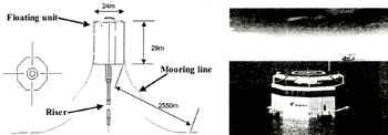
There is a buoy of spar type set upright (long and slender form like a stick) as what was considered not to oscillate in the severe ocean field. Based on the concept of the form of spar type. OTEC plant equipment and accommodation field were secured as design conditions, and it was decided for construction purposes to adopt the structure of Semi-Submergible type octagon column shape formula that has easy form. Moreover, since the center of gravity becomes low with a riser and a meta-center becomes large, the characteristics of motion that were excellent in wave are expectable. The general arrangement of the offshore floating unit is shown in Figure 1 and principal measurements and plants are shown in Table 2.
The offshore structure consists of floating unit, mooring systems and riser. The inside of floating unit consists of the power generation plant, an engine room, an electric room, accommodation and ballast rooms.
| (Enlarge: 27KB) |
 |
Figure 1. General arrangement of the offshore floating unit
CALCULATION OF MOTIONS
Equations of motion
| (Enlarge: 9KB) |
 |
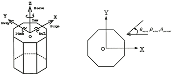
Figure 2. Descartes coordinate systems
Figure 2 is shown in Descartes coordinate systems.
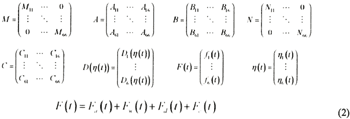
The equation of motion of the offshore floating unit for OTEC Plant is written as follows.
Where,
| (Enlarge: 16KB) |
 |
Where, M shows the total mass of floating unit, A shows added mass coefficients, B shows damping coefficients, C shows restore coefficients, N shows the drag coefficients in consideration of viscous influence, D shows the tension the tension acting on mooring lines, F shows the external forces. Like equation (2), the external forces involve wave exciting force, wind force, wave drift force and current force η is displacement of motions.
|