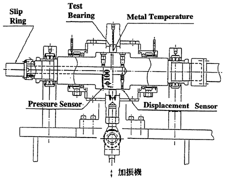
Fig. 7 Testing Equipment Specimen Part
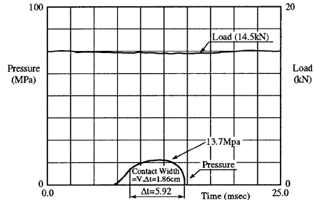
Fig. 8 Oil Film Pressure Distribution of Existing Diaphragm Type Sensor
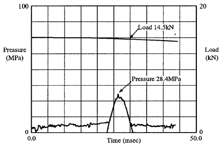
Fig. 9 Oil Film Pressure Distribution of O-Ring Type Sensor
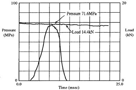
Fig. 10 Oil Film Pressure Distribution of Conical Spring Type Sensor
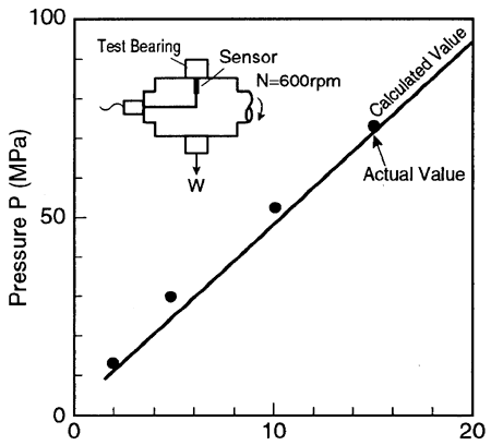
Fig. 11 Comparison of Measured Pressure and Calculated Value
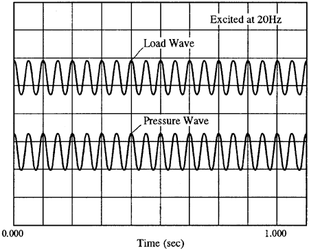
Fig. 12 Wave Comparison Example of Load Excited at 20Hz and Pressure
Main shaft speed is measured with electromagnetic pulse of gear attached to the shaft.
Comparison of raw data obtained in each sensor's oil film pressure measurement is shown in Fig.8 through 10.
Fig.8 shows the data obtained by existing sensor of diaphragm type. Please note that its maximum measured pressure is approximately 13.7MPa with bearing load of 14.5kN. Comparing this pressure with evaluation pressure of 70.3MPa which is derived from working load, the former is less than 1/5 of the latter, which is considered to be very poor result. This may be determined to be caused by insufficient response at pressure leading part.
Fig.9 shows the data obtained by the experimental sensor with axial force detection method and O-ring seal. As in the case with existing sensor, satisfying pressure measurement is not achieved. In this case, measuring pressure is as low as 28.4MPa with bearing load of 14.4kN. The reason for decreased measuring pressure is considered to be unexpected O-ring movement due to compression caused by raised pressure in O-ring groove.
BACK CONTENTS NEXT