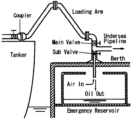
Fig. 8 Schematic view of the waterhammer suppression device
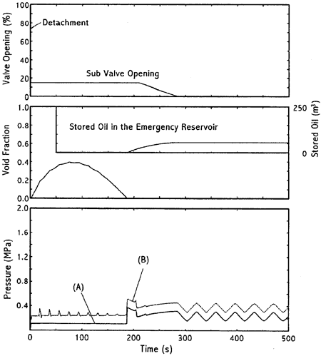
Fig. 9 Weakend pressure transient by the waterhammer suppression device
丂
The valve operation is also easy. The process of valve closing after the cavity is formed in the pipe is as follows. When the oil return is seen at the emergency reservoir, wait another 20 s in this case, which is the time duration for the pressure wave to go and back in the pipeline or the time duration until the first high pressure peek is over. Then the sub valve is closed slowly. No air is trapped in the pipeline in this case.
As to the berth side, the same effect is expected by equipping only one pair of main - sub valve at the point where the three lines from loading arms are united to the undersea line. Therefore, the newly proposed system is simpler than equipping valves at the end of each loading arm and operating them individually.
丂
4. CONCLUSION
丂
(1) In order to prevent an excessive pressure rise by waterhammer, the elevation of oil surface in the shore tank from the coupler should be taken notice in actual operations. The absolute pressure rise by waterhammer are larger at the undersea pipeline than at the emergency valve. The pressure rise at the undersea pipeline should be paid attention in the pipeline design.
(2) In the case the coupler is detached suddenly, the slow closure of the valve is sometimes better than the rapid closure in view of suppressing pressure rise though the effect is not accurately predictable.
(3) A device to suppress waterhammer for the loading system is proposed. It is expected to be simpler and safer than equipping valves in the coupler.
丂
References
丂
[1] Wylie, E. B. and Streeter, V. L., "Fluid Transicnts", McGraw-Hill, (1978)
[2] Betamio de Alemeida, A. and Koelle, E., "Fluid Transients in Pipe Networks", Computational Mechanics Publications. (1992).
[3] Yamamoto, K., Outa, E., Sano, M., Miwa, T. and Okada, K., "Examination of Discrete Cavity Models for Waterhammer Analysis Including Column Separation in a Horizontal Pipeline", Trans. of JSME, 55-513, (1989), pp.1296-1301. (in Japanese)
[4] Simpson, A. R., and Wylie. E. B., "Numerical Comparison of Pipe-Column-Separation Models", J. Hydraulic Engng., 120-3, (1994), PP.361-377.
[5] Liou, C. P., "Calculations of Transients in Batched Pipelines", Proc. of 4th Int. Conf. on Pressure Surges, (1983), pp.13-25.
[6] Wylie, E. B., "Simulation of Vaporous and Gaseous Cavitation", J. Fluids Engng., 106, (1984), pp.307-311.
[7] Wiggert, D. C. and Sundquist, M. J., "The Effect of Gaseous Cavitation on Fluid Transients", J. Fluids Engng., 101, (1979), pp.79-86.
[8] Baasiri, M. and Tullis, J. P., "Air Release During Column Separation", J. Fluids Engng., 105, (1983), pp.113-118.
[9] Swaffield, J. A., "A Study of the Influence of Air Release on Column Separation in an Aviation Kerosine Pipeline", Proc. Inst. Mech. Engrs., 186, (1972), pp.693-763.