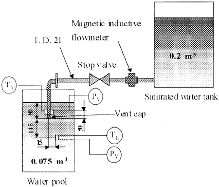
Figure 1 Experimental apparatus
丂
Apparatus
丂
The apparatus used in the experiment is illustrated in Fig. 1. It consisted of a 0.2 m3 high-pressure saturated water tank which was equivalent to a pressure vessel, a 0.075 m3 pool-water tank with an inner diameter of 406 mm and a height of 800 mm which was equivalent to a water-filled containment, and a vent tube with an inner diameter of 21 mm and a length of 1.4 m connecting the two tanks. High-pressure saturated water was discharged into the pool tank from the vertical vent tube with a cap at the top of the vent. The vent tube outlet diameter (or nozzzle diameter), dV, and length, lV, could be changed by using caps with holes of different diameter and different thickness (Fig. 2).
丂
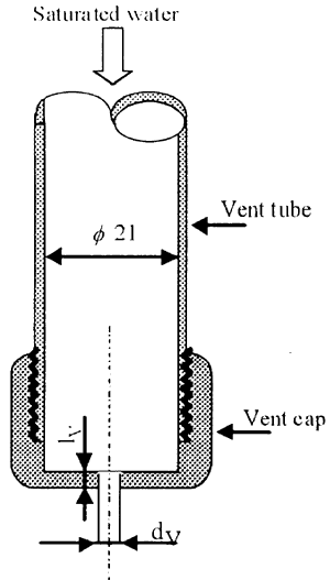
Figure 2 Nozzle at outlet vent
The pressure in the air space of the pool tank was atmospheric. The pressure and temperature in the vent tube and pool tank were measured by semiconductor pressure transducers (with a natural frequency of 40 kHZ and bidirectional span of 0.5 MPa) and thermocouples, respectively. The output signals from these sensors were first transmitted to it Fast Fourier Transform (FFT) analyzer, then to a personal computer. The water mass flow rate was measured by an electro induced mass flow meter. The sampling rates of the data acquiring system are 10 kHZ for pressure measurement and 10 Hz for temperature and water flow rate measurements. The phenomena were observed with a high-speed video camera that operated at 2,000 frames per second, synchronized with the pressure and temperature measurements. A trigger signal provided a starting signal to the FFT and the camera. Experiments were performed by using different vent cap hole diameter (4, 5, 6 mm), nozzle length (1, 3.8, 10 mm), pool water temperatures (20-70 亷), and discharging saturated water pressures (3-10 bars).
丂
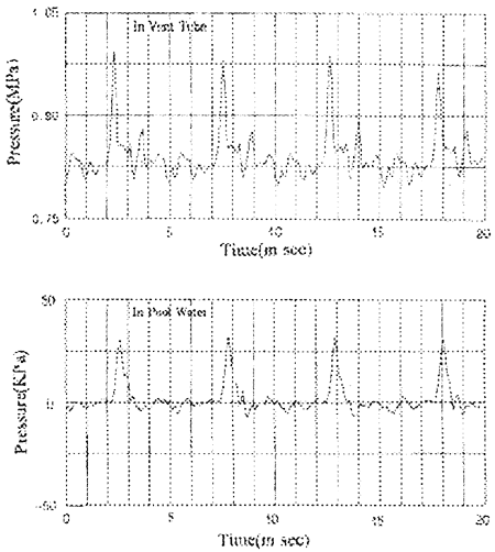
Figure 3 Pressure traces in vent tube and in pool water
(dV = 4 mm, PH = O. 84 Mpa, TL = 50 亷, lV = 3.8 mm)
丂
Experimental results
丂
Figure 3 shows the typical record of the pressure traces in the vent tube and the pool water. The pressure in the vent tube oscillates periodically and is synchronized with the pressure of the pool water. The results show that a flashing oscillation (FO) occurs when high-pressure saturated water is discharged into pool water under specified experimental settings. Figure 4 shows video images of this phenomenon. The occurrence of flashing oscillates between a point very close to the vent hole and a point some distance away. We name the flashing very close to the vent hole "Phase A", and the flashing at some distance from the vent hole "Phase B". As shown in Fig. 5, the pressure in the vent varied according to the FO and piked when pressure oscillation appeared in the region of Phase B. The physical behavior of flashing depends on the thermodynamic state of the fluid and on the geometry of the outlet vent. Some experimental studies on flashing, using an orifice and a nozzle, have shown that a vapor bubble could not grow in a short nozzle and that flashing (or vaporization and atomization) of the discharging water took place at some distance from the nozzle [1, 2]. The results of these studies explained that FO phenomena might depend on the geometry of the outlet vent.
A test using two vent tubes, the length of which differed by 10 m and 2.0 m from the original one showed that the physical behavior of the FO was consistent under different vent tube length conditions. As, the FO phenomenon was influenced weakly by the length of the vent tube, the frequency of the FO depended on the control volume, consisting of steam bubbles in the pool water and a part of the outlet space of the vent tube. The oscillation of the pressure and flashing location might have been caused by balancing action among the supply of saturated water, flashing in the control volume, and steam condensation on the steam-water interface, as shown in the Fig. 4.
丂
丂
丂
BACK丂丂丂CONTENTS丂丂丂NEXT
丂