An analysis report about the composites of the soot deposited on the inner surface of air manifold after the explosion in case (4) mentioned previously was available. According to the report, the major combustible material was probably system oil that lubricates main bearings in crankcases because the soot contained the high level of calcium and zinc that feature system oil. However the possibility of contamination of fuel oil, cylinder lubricating oil and lubricating oil for air compressor which provides high pressure air to air reservoirs into air manifold also cannot be ruled out, because if these materials were completely burnt, the soot would not be produced and remained.
Hereinafter, the ways of penetration of combustibles into air manifold will be discussed.
3.1 Probable Combustibles
As mentioned above, combustibles that caused the explosion could not be definitely identified, although existence of system oil in manifold was proved by analysing the composites of soot deposited in air manifold. Therefore, all possible combustibles in diesel engines will be examined.
The contamination of system oil into air manifold is considered to be through the starting air control valves connected with pipes opened to crankcase, On the other hand, air compressors are usually lubricated by injecting small quantities of lubricating oil directly into cylinders. Because all oil will not be removed, a portion will be carried into the air system.
As for fuel oil, the only way of its carryover into air manifold will be the leak of incompletely burned gas from cylinder due to malfunction of starting air valve.
3.2 Maximum Temperature and Duration Time in Rapid Compression Model
The air reservoirs are usually filled with a large volume of high-pressure air and are connected through a valve to dead-ended starting air manifold, initially at low pressure.
To start the engine, the valve is opened, the high-pressure air is to be admitted into the air manifold. It was found in a similar experiment by G. M. Faeth [6] that the gas originally in the downstream of the valve was swept toward the end of the pipe with little mixing, and compressed. The work of compression increases the temperature of downstream gas, which, under certain condition can cause ignition of any combustible material present at the end of the air manifold. In adiabatic compression model, the temperature of compressed gas can be expressed as follows:
where
T1: absolute temperature before compression
T2: absolute temperature after compression
P1: initial pressure
T2: Final pressure
k: ratio of specific heat. For air k=1.4
Consequently, for typical starting system with initial pressure of 0.1 MPa , initial temperature of 45℃ and final pressure of 2.5 MPa, the possible maximum temperature could reach 525℃ as shown Figure 4.
Figure 4. Theoretical Relation between Temperature and Pressure in Adiabatic Compression
However experimental results showed the actual gas temperature could be reached is not only dependent on final pressure but also affected by pressure rise rate in practical system. Higher pressure rise rates means that the compression process occurs so rapidly that there is little heat loss and the maximum temperature can be considered, as perfect adiabatic change, just depends on final pressure for a given initial pressure and temperature. But, as the pressure rise rate is decreased, high final pressures are necessary to attain a given temperature, this reflects the increased heat loss during slower compression process.
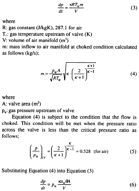
Assuming that the gas pressure in the air manifold increases at a constant rate for the major portion of the charging process, a simplified analysis was introduced to estimate this constant pressure rise rate. Pressure rise rate can be derived from the equation for conservation of energy in air manifold by assuming that the flow through valve is adiabatic.
It was written as:
