Fig. 1 Plant concept selection parameters
丂
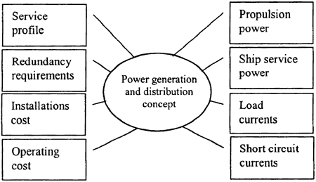
Voltage level of power generation is selected so that load current and short circuit levels are kept within limits of available components. In case total power is not too high, low voltage system is normally the most cost-effective solution. With increasing total power the power generating voltage will increase accordingly. 11 kV is the highest voltage level that has been used so far, but with increase of total installed power even higher voltages become feasible.
Distribution system design has major effect on both material- and labor cost of electric distribution system construction. Generally all big consumers, such as thrusters and compressors, should be connected directly to the power plant main bus. In large cruise vessels distribution system is typically built of separate network sections for each fire zone. In this case also power transmission is normally made at higher voltage level to minimize losses and cabling cost.
丂
2.2 Propulsion Drive
2.2.1 Drive types
Electric propulsion drives have been made by practically all available techniques. In simplest case direct driven synchronous or asynchronous motor combined with a CP-propeller may be used. In modern systems, however, a frequency converter drive is used in high power main propulsion applications.
Electric propulsion systems based on DC-drive have been used over 60 years. About 20 years ago AC-drives came to the market and are used practically in all applications today.
At power range up to four megawatts a low voltage PWM drive is most common solution. With higher powers up to 8 MW medium voltage PWM drive together with asynchronous motor has been more or less standard solution.
Higher power drives are mainly based on two techniques, cycloconverter or LCI. Cycloconverter changes constant frequency input voltage to a lower variable speed frequency directly making it ideal for low speed drives such as directly connected main propulsion. Cycloconverter is able to operate at unity motor power factor, which is beneficial for motor design in case of podded propulsion. LCI in turn is based on a DC intermediate circuit and can be used at larger frequency range, but on the other hand low speed operation requires special control methods.
Future development of drives will make possible even higher shaft powers. On the other hand new drive types such as medium voltage DTC (Direct Torque Control) drives together with synchronous motor may replace existing high power drive techniques to some extent.
丂
2.2.2 Electric propulsion drive
All of the drive types described above are widely used in various industrial processes requiring high dynamic capacity. From this point of view propulsion of open water ship is a relatively simple task for any type of frequency converter.
On the other hand a propulsion drive must be able to operate in a weak supply network. Propulsion power may be up to 95 % of total consumption, which means that it is the only consumer capable of protecting the whole system. Being the major consumer propulsion drive is also the main source of harmonic currents.
Working together with the supplying power plant and distribution system is the most demanding task of an electric propulsion drive control system.
丂
2.3 CONTROL OF HARMONICS
The most common solutions for decreasing harmonics have been to use filter circuits tuned to certain harmonic frequencies or to use rotating converters to supply sensitive consumers. Filters need careful design work due to possible network resonances. Rotating converters in turn require extra equipment and cabling for power distribution.
Higher pulse numbers in frequency converter drives will decrease harmonics in the load current, but on the other hand mean the use of extra components and resulting higher costs.
Duplex reactors may be used to build separate propulsion and ship service bus in main power station. This solution will provide very low harmonic content in the ship service network.
By correct dimensioning of power plant generators and propulsion drives it is often possible to maintain harmonics at the desired levels without resorting to any of the above-mentioned additional measures.
All the above solutions have their own benefits and the method to be used shall be decided case by case depending on the application.
丂
2.4 SYSTEM Simulations
Power plant and drive system supplier should have proper knowledge and tools to design the drive and power plant in such a way that specified harmonic levels, frequency and voltage variations are not exceeded.
Numerical calculations based on modeling of network components as well as propeller and ship hydrodynamics provide an efficient design and research tool for a system designer. System simulation may be used to study various operations and phenomena, including:
丒 System efficiency
丒 Voltage wave form
丒 Total harmonic distortion
丒 Starting of large consumers
丒 Crash stop
丂
3. HISTORY OF THE AZIPOD PROPULSION CONCEPT
丂
The original idea for the Azipod system was developed when the Finnish Maritime Administration began to seek better solutions for the operation of icebreakers in ice channels. An important feature of an icebreaker is that it must be able to break out of an existing ice channel. This is important when the merchant ships that are being assisted, are using the ice channel and the icebreaker has to move around the operational area. To overcome this problem, the idea of a propulsion motor that could direct the thrust to any direction was created. The idea was presented to ABB and the concept of Azipod was drafted and patented.