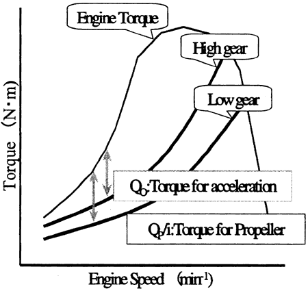
As a general feature of a propeller, driving force T will increase in proportion to the increased revolutions of a propeller. The condition of a propeller during sailing is shown in a formula (2) below;
丂
Qo = QE - QP/i (2)
QE: Engine output torque
QP: Propeller shaft torque for sailing at steady boat speed
Qo: Torque for hull acceleration
i: Reduction gear ratio of marine transmission
丂
To obtain increased propeller revolutions, Qo must be increased. That is, for a propeller designed to reach the maximum boat speed at the engine rated revolutions, the engine is accelerated at the larger reduction gear ratio, as shown in Fig 2, in the engine low revolution stage, then it is shifted at the optimum engine revolutions. However, during shifting, like manual transmission automobiles, shift shock generally occurs due to intermittent power transmission.
By introducing electrically controlled techniques into marine transmission, acceleration without shift shock will be implemented by properly controlling automatic shifting and hydraulic fluid pressure.
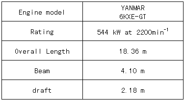
The resulting calculation of acceleration performance through the use of 2 speed marine transmission shows that acceleration time can be shortened by 25 - 30%. We use the propeller efficiency ratio in the calculation so that the ratio can be determined by the forward coefficient of a propeller that will frequently change according to the condition of the hull. The main points of the hull and engine are illustrated in Table 1.
丂
Fig. 2 Torque Properties
丂
2.2 Improvement in deceleration properties with crash astern
Crash astern of a ship is performed by shifting the clutch from forward to backward in a short time, equivalent to operating the brakes of vehicles. Generally, if you suddenly shift, the engine will be overloaded, causing engine stall and making it impossible for a ship to quick deceleration. Therefore, devices such as those that automatically switch on/off the clutch to soften engine load are developed. However, they will require quick deceleration performance because of longer time for deceleration.
The equation of motion of a shaft during crash astern is shown below:
丂
QB = (2兾/60)丒I丒dn/dt + QP0 (3)
QB: Load torque of a propeller shaft
QP0: Propeller torque as load due to fluid power
I: Inertia moment of a propeller in water
n: Propeller revolutions
丂
In the formula (3), the first item on the right shows torque accelerating propeller revolutions.
If crash astern in which sudden switching from forward acceleration to backward acceleration is performed, changes in propeller revolutions dn/dt are remarkably increased, and QB may exceed Engine torque QE丒i. This means that the torque transmitted to the propeller of an engine exceeds the load torque on the propeller shaft, causing a decrease in engine revolutions, or serious engine stall. In this case, lowering dn/dt further in formula (3) can prevent engine stall. For slipping clutch, lowering hydraulic pressure can be implemented by reducing dn/dt. However, higher hydraulic pressure may cause the seizure of friction boards this time, while lower hydraulic pressure may cause longer time for anchor because no power is transmitted to the propeller.
Fig.3 shows general limits to the seizure of friction boards. The left side in the solid lines is the "safe area" during fitting, and the areas below the broken lines are the "safe area" during continuous slip.
Unit absorption factor of a board 兠 is determined by formula (4), and the maximum hydraulic pressure at each engine revolution is given.
丂
兠=兪亊P1亊v (N丒m/cm2/s) (4)
兪: Dynamic friction coefficient
P1: Friction plate surface pressure (N/cm2)
V: Peripheral velocity (m/s)