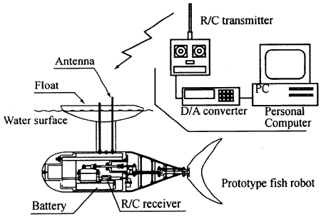
In the operation, a wood float is set at upper side of the body (see Fig.5), thus; the prototype fish robot swims a constant depth. In order to adjust balance of gravitation and buoyancy, weights made of stainless steel are located at a head and rear side of the body.
丂
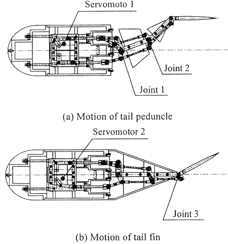
2.3 LINK MECHANISM
Figure 3 shows a link mechanism in leaning the joints. For acquiring smooth motion like fish, it is better to have as many joints as possible. However, in order to have a simple structure, the prototype fish robot has three joints with a unique link mechanism.
Servomotor 1 moves Joints 1 and 2 as shown in Fig.3(a). Flexible motion is realized by adjusting length of crank arms and rods. Servomotor 2 moves Joint 3 through free crank arms located at Joints 1 and 2 as shown in Fig.3(b). Thus, the tail peduncle and tail fin are moved independently and optionally.
丂
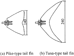
2.4 TAIL FIN
Two types of tail fin are manufactured as shown in Fig.4. One is pike-type and the other is tuna-type. They are made of hard wood board. They have different shapes as described above. Also, the pike-type tail fm has plane cross-section comparatively. The tuna-type tail fin has streamlined cross-section, similar to airfoil shape. Side-projected area of the pike-type tail fm is determined from size of a real pike shown in Fig.1(a). Side-projected area of the tuna-type tail fin is equivalent to that of the pike-type tail fin, and it is determined from similar figures of Fig.1(b).
丂
2.5 CONTROL SYSTEM AND MOVING PATTERN
Figure 5 shows a control system for the prototype fish robot. The servomotors are controlled by a personal computer with an R/C transmitter and a D/A converter.
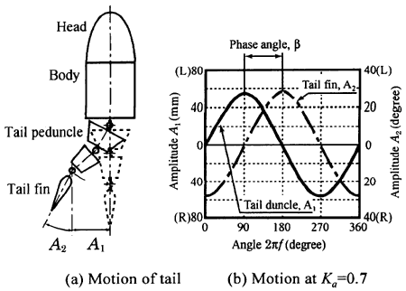
Figure 6 shows outline of a moving pattern. A simple sine wave is used at following experiments, though various moving patterns can be set optionally by a control program. Amplitude of tail peduncle from the central axis of body, A1 (mm), and that of tail fin from the same axis, A2 (degree), are obtained by the following equations.
A1 = KaA1max sin2兾ft (1)
A2 = KaA2max sin (2兾ft - 兝) (2)
Here, f is frequency (Hz). t is time (sec). A1max and A2max are maximum amplitudes limited by the link mechanism. Ka is amplitude factor (set to 0乣1). They are set at A1max = 80 mm, A2max = 30 degrees, and Ka = 0.7, at the following experiments. 兝 is phase angle between the tail peduncle and the tail fin.
丂
3. PERFORMANCE OF THE FISH ROBOT
丂
3.1 EXPERIMENTAL METHOD
Swimming speed of the prototype fish robot is measured at a water tank which has 8 m length, 0.9 m width and 1.2 m depth. After the pre-swimming of about 4 m to have a stable velocity, the measurement to get the swimming speed begins. The average speed is calculated by measuring time in which the fish robot swims 1.9 m.
丂
3.2 EFFECTS OF FREQUENCY
Figure 7 shows experimental results of the relationship between frequency, f, and swimming speed, V, at the phase angle, 兝, of 60 degrees or 90 degrees. In the figure, swimming speed using the pike-type tail fin is higher than that of the tuna-type tail fin, in the range of lower frequency.
丂
Fig. 3 Link mechanism
Fig. 4 Tail fins
Fig. 5 Control system
Fig. 6 Outline of moving pattern