These results are shown in Table (c) of Fig. 1. This table shows the noise level of 3 engine loads in 3 cases such as 1) No counter measure, 2) Countermeasure (1) and 3) Countermeasure (2). From those results, the countermeasure (1) gave the reduction effect of 4dB at the measuring points A and B which are near to the charging air pipe and the air cooler housing. However the reduction effect was little at the measuring point C which is near to the scavenging air receiver without lagging. The effect of 10乣14dB was obtained by the countermeasure (2) added to the countermeasure (1).
This result shows that the reduction effect is small in case of partial treatment and large in case of full treatment. For example, considering the case of gathering 10 machines and assuming that the power level of each machine is 100dB and the reduction effect of lagging applied to one machine is 20dB, then the relation between the total reduction effect and the treatment amount are shown in Table2.
It is understood that the large reduction of lagging effect does not appear until 90% treatment.
丂
4. DESIGN OF RESONATOR AND ITS APPLIED RESULT
丂
4.1 Design of Resonator
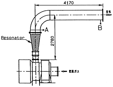
The countermeasure of the lagging mentioned above is very effective but cost increase is inevitable. Then in this chapter, the noise reduction equipment with the resonator (call it resonator after this) is applied to the test turbocharger (NA48/S type) and the reduction effect in the land operation is described.
丂
Fig. 6 Equipment with resonator
Fig. 7 measuring points
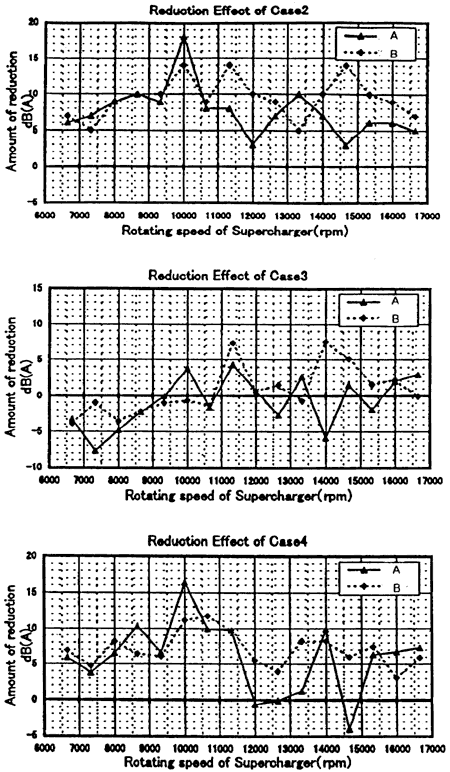
Fig. 8 Noise reduction of each equipment
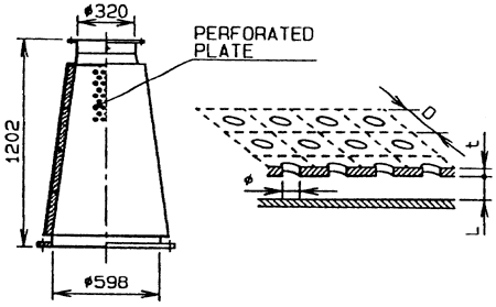
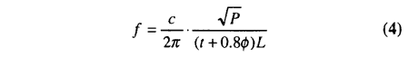
where t is the plate thickness, L is the height of the space, c is the sound speed and P is the perforated ratio defined by 兾冇L/4DL
D is the diameter of hole.
The dimensions were determined like that the design frequency coincides with the dominant frequency of noise.
丂
4.2 Applied result in bench test
The confirmation bench test was carried out by using the original horn and three different horns with resonator in order to know the reduction effect of the resonator.