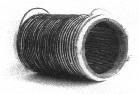
Fig. 2 Induction heating unit
Fig. 3 The ZCS high frequency inverter in complex resonance
丂
And while passing the induction heating unit PM is burned instantly and reduced. Therefore the filter is not clogged.
Fig. 2 shows the outline of induction heating unit. This unit is composed of metallic filter for trapping PM and the working coil for induction heating. For the metallic filter, both a corrosion-resisting metal and a magnetic material are required. Accordingly the stainless steel of SUS430 is used for metallic filter.
丂
Fig. 4 Principle of overlapping commutation ZCS
Fig. 5 Switching operation modes
丂
3. POWER SUPPLY FOR PM REDUCTION SYSTEM
丂
PM reduction system utilizes high frequency induction heating and high frequency inverter is used for that power supply. The ZCS (Zero Current Switching) high frequency inverter proposed for power supply is shown in Fig. 3. This inverter realizes a stable operation in the wide range of load, because of using complex resonance. Furthermore a heavy current is supplied to the load suppressing current of switch by forming a tank circuit. And an overlapping commutation ZCS, as soft switching, is utilized to the proposed inverter. Fig. 4 shows the principle of an overlapping commutation ZCS, and relation to the switching modes. And the switching modes of the proposed inverter are shown in Fig. 5. The switching modes of proposed inverter are classified to seven modes due to the switching condition of the switches of S1乣S4 and diodes of D1乣D4 as follows.
丂
MODE (a): S1-S2 single conduction mode
MODE (b): D1-D2 single conduction mode
MODE (c): D1-D2, S3-S4 double conduction mode
MODE (d): S3-S4 single conduction mode
MODE (e): D3-D4 single conduction mode
MODE (f): S1-S2, D3-D4 double conduction mode
MODE (g): OFF mode
丂
The values of current of id and is which flow through inductance of Ld and Ls respectively, do not jump instantly. In Fig. 4, an overlapping time occurs by the continuity of current in Ld and Ls. And the value of each switching current (il-i4) is expressed as follows in order to derive from the symmetry of full bridge inverter.