Fig. 2 Flow Diagram
丂
As raw materials, hydrogen and nitrogen are supplied from cylinders and mixed with process gas from ammonia separator, then heated to about 300亷 before entering the ammonia synthesis reactor in which hydrogen and nitrogen react with each other to form ammonia by the following simple reaction formula at 1 MPa[gauge] and 350亷 with the aid of ruthenium catalyst:
3H2 + N2 = 2NH3
Process gas from the rector which contains about 3.6 percent of ammonia is cooled down to about 30亷, then fed into the ammonia separator. Ammonia is absorbed in water and separated as aqueous ammonia from un-reacted process gas (mixture of hydrogen and nitrogen) by absorption with water. Process gas is then recycled to the ammonia synthesis reactor via compressor and a mixer. Ruthenium catalyst of 300g is packed in the ammonia synthesis rector.
Ammonia synthesis temperature is thyristor controlled. The pressure and flow of hydrogen and nitrogen are controlled by mass flow controllers and a pressure controller. The flow of recycled process gas is also controlled by a mass flow controller. Reaction temperature is controlled by electric heaters at the inlet of the reactor and center of the catalyst bed. The rector is installed in the electric furnace to keep the catalyst bed at constant temperature avoiding heat losses from the rector. Ammonia at the outlet of the rector is analyzed using a mass spectrometer. The whole experimental device is operated, controlled and monitored by a personal computer. Operating parameters are shown in Table 1.
丂
Table 1 Operating Parameters
丂
2.3 Experimental Device
Fig. 3 is a photo of the skid mounted experimental device. Ammonia synthesis rectors are at the center of the skid. A control panel is installed adjacent to the local gauge board.
丂
2.4 Results
The concentration of ammonia at the exit of the rector is 3.6 percent v/v which is about 50 percent of equilibrium conversion at these operating conditions and higher than expected. Aqueous ammonia of 0.7 g/h is obtained at 5 percent w/w solution as the product. Ammonia in the process gas at the exit ammonia separator was not detected. That is, the yield of ammonia was almost 100 percent. Deterioration of the catalyst was not observed during operation of about 1,400h. The control system worked well to keep all operating parameters such as flows of each fluid, temperatures, pressures and others at set values.
丂
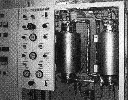
Fig. 3 Photo of the Experimental Device
丂
3. APPLICATION TO SHIPS
丂
Based on the data obtained by experiments, we studied the shipboard application of this ammonia unit. Selected model of the ship is PANAMAX 74BC.
丂
3.1 Basis of Study
The basis of the study is provided in Table 2. Gas flow of 47,500m3N/h is rather small but NOx content of 1,500 ppm is much higher, comparing to stationary sources on shore. Net ammonia consumption figure is about 44kg/h.
丂
Table 2 Basis of Study of Ammonia System for PANAMAX 74BC
丂
丂
丂
BACK丂丂丂CONTENTS丂丂丂NEXT
丂