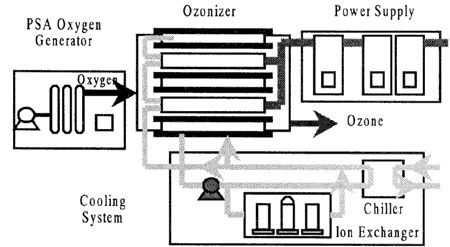
(a) Schematic diagram of ozone generation system

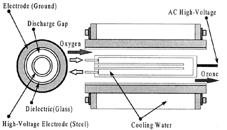
(b) Structure of the novel ozone generation tube
Fig. 1 Silent discharge type ozone generation system
A schematic circuit diagram of the ozone generation system, which incorporates the high-frequency resonant inverter, is depicted in Fig. 1 (a).
Main blocks in the experimental installation include PSA (Pressure Swing Adsorption) oxygen generator; silent discharge type ozone generation tube; voltage-source high-frequency inverter type power supply control system and cooling system. Oxygen generator might be unnecessary in ship applications since there is now demand for ozone of high concentration. In this case, ozone can be produced directly from air, however efficiency of this method much lower.
Internal structure of the silent discharge ozone generation tube used in experiment is illustrated in Fig. 1 (b). It has cylindrical structure with ground electrode outside and high voltage electrode inside. Ground electrode is covered by dielectric layer (quartz glass) as dielectric barrier between electrodes so as to provide silent discharge conditions in the gap.
When applied voltage achieves the certain level defined as discharge starting voltage, it tears away electrons from the oxygen molecules and provides them kinetic energy sufficient to destroy another molecules into ions that starts silent discharge in the discharge gap. During this period, there are two reactions taking place simultaneously: oxygen to ions distraction and oxygen or ozone recombination. The same discharge phenomena occurs both, during the positive and negative voltages. At the same time, ozone is synthesized at this time by another way, under the influence of the ultraviolet light generated within the discharge gap. If the applied high-frequency AC voltage between two AC tube electrodes is much lower than silent discharge starting level, the discharge phenomena doesn't occur and reveals a partial discharge.

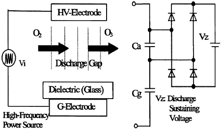
Fig. 2 Equivalent electric circuit for silent discharge tube.
During discharge period, the voltage drop on the discharge gap remains constant, which is defined as discharge sustaining voltage and only voltage on the dielectric layer changes upon the applied voltage.
From a practical point of view, nonlinear capacitive equivalent electric circuit model of the ozone generation tube can be represented as in Fig. 2. The discharge sustaining voltage is represented by DC voltage source Vz, which is connected to full bridge diode rectifier circuit. In actual, Vz changes upon influences of external environment conditions such as temperature, air pressure, humidity and so on. Discharge gap between two AC electrodes is represented as an air gap capacitance Ca in series with the capacitance Cg determined by the glass material substrate.
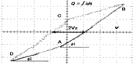
Discharge sustaining voltage Vz and equivalent electric circuit parameters Ca and Cg can be estimated from Lissajous figures taken by oscilloscope on the silent discharge load, such as shown in Fig. 3
The lines with more gentle inclination (D-A, B-C) on the Lissajous figure, which represent discharge period, are defined by capacitance of the dielectric substrate and equal to
α = tan φ1 = Cg・Sl (1)
where; Cg capacitance of dielectric barrier,
Sl ; area of Lissajous figure.
On the other hand, the inclination in non-discharge period (A-B, C-D) can be derived as

where; S - area of electrode

Fig. 3 Lissajous figure of discharge in load.
BACK CONTENTS NEXT