丂
4.2 Test on a ship board
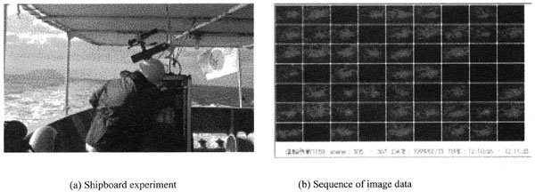
The test on a ship board was conducted on Yuge Maru in Setonaikai, inland sea in cooperation of the Yuge National College of Marine Technology. Figure 4 shows (a) Shipboard experiment on rear board. The main part of data acquisition system was covered with plastic case to protect from the salinity. During the daytime, the weather was fine, forming stream was very bright. Figure 4 (b) shows a sequence of image data, where the surface illuminated by the laser can be clearly identified in bright foaming waves with appropriate gate operation of tens nano-second and narrowband filter of width of 10 nano-meter. The ability to discriminate the signal from the background was confirmed.
The wave motion considerably influenced the signal intensity. During the cruise, we have not encounter apparent oil pollution. The system suffered from electrical noise probably due to the electrical mis-matching and a supply so that the data acquisition was occasionally disturbed.
丂
4.3 Flight tests
The flight tests were conducted twice in cooperation with the Electronic Navigation Research Institute. The first overflight above the Institute was to verify detect-ability of the known target of a role paper. The second was to verify the performance for marine observation.
The proto-type of aerial lidar system of about 43kg in total weight was installed on the Beach Craft with maximum 6 members including a pilot and a co-pilot. A monitor camera recorded visible image and flight data.
The aerial system also incorporated a target location function by GPS(global positioning system) which permitted near real time reporting with latitude, longitude, and time and annotating them directly alongside of the imagery.
Figure 5 shows an airplane, a bottom hatch, a part of an aerial system with a fluorescence lidar, infrared camera and visible camera. On 14th March 2000, the flight course was taken to the Sea of Japan to observe the sea surface and coast lines.
Accidentally , the pilot found a few patches of spills off Oki island near the wrecked part of Nakhodka from the altitude of 1000 feet. During overflight from 11:03 to 11 :28am we tried to observe the spills 4 times with the imaging lidar and visible camera. The upper image of Figure. 6 shows a picture of oil spill taken by visible camera, the lower image shows an image of the lidar system with narrow band filter of 405nm. But we could not succeed to get the fluorescence of oil illuminated by the laser. It was difficult to shoot the patch of about 10m, because of irregular movement of an airplane and the low repetition rate of the laser (10Hz).
On 15th March 2000, in the afternoon on way to the Sea of Japan, we conducted a flight test over Lake Biwa. Figure 7 shows a sequence of images measured on Lake Biwa from the altitude of 1000ft.
In this case, the surface illuminated by the laser was clearly marked, a signal included Raman scattering of water and the fluorescent matter.
丂
Table 1 Data of the flight for the Sea of Japan
1] Course: 14th March 2000 am; near the wrecked part of Nakhodka (N37, 14. 4, E134. 24. 9)
2]Course: 15 th March 2000 pm; Lake Biwa, coast lines of Mikuni and Kasumi along the Sea of Japan
3] Altitude: 1000ft
4] Speed: 150knot
5] Laser: Third harmonics of Nd:YAG (355nm)
Max.power; 11mJ/pulse,
Beam divergence; 3mrad.
Repetition; max. 10HZ
6] Filter; Band pass filter F405 (CW 405nm, FWHM, 10nm)
Notch filter F355(CW 355nm, FWHM, 10nm)
7] CCD: 659*494pixels
8] Image intensifier: gate 3ns 乣 CW, 0.8 乣
1.2x10⁴lm/m2/lx
9] UV lens: f50.4mm, F3.5