Then, the injection period is 3.6 ms for standard injection of n-Tridecane (X CO2 = 0.0), and 3.8 ms for XCO2 = 0.4, 4.5 ms for XCO2 = 0.6 and 6.5 ms for XCO2 = 0.8. The fuel was injected perpendicularly into the chamber. The distance between nozzle tip and the lower side cylinder wal1 is 96 mm. The overall excess air ratio 1 is 25. For the operation of RCEM with compression ratio of 15, the ambient atmosphere in the cylinder reaches 750 K in temperature and 3.2 MPa in pressure at the time of injection, that is 5.0 deg. before TDC.
丂
Figure 9 shows the P-T diagram for the mixed fuel of XCO2 = 0.6 in RCEM, As shown here, the decompression during fuel injection process does not reach two phase region. Thus, we could not get flash boiling of CO2 for the injection. Thereafter, the injected fuel should be heated up to the ambient temperature from the surroundings. It is expected that the mixed fuel must be vaporized promptly owing to the selective flash boiling process of liquefied CO2 component.
A quartz glass window is installed in the cylinder head to allow taking spray and flame photography by 16 mm high-speed camera (NAC: E-10). In this experiment, shadow photography for vaporizing spray and combustion flame were taken with Ar1 laser (CHOHERENT: INNOVA 70-4, maximum power 4W) light of 514.5 nm in wavelength. Photographing speed is 6000 fps and a color negative film (Kodak: VISION200T) is used. Further, two color method was applied to direct photograph images in order to assess flame temperature and KL factor inside the combustion flame.
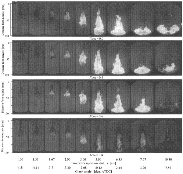
SHADOW PHOTOGRAPHY - Figure 10 demonstrates the temporal changes in typical shadowgraph photographs of the spray and the frame for each CO2 mole fraction. At time t = 1.00 and 1.33 ms, fuel concentration seems to be diluted in the spray downstream region for XCO2 = 0.6 and XCO2 = 0.8. At the timing around 1.67 ms, the visible flame appears near the mixing region at the tip of the main liquid jet for XCO2 = 0.0, while it appears near the downstream region or the spray tip region for larger CO2 mole fraction conditions. In the case of XCO2 = 0.0, 0.4 and 0.6, the visible flames cover the whole spray region during the main combustion period, thereafter the flame is mainly spreading near the wall.
Fig. 10 Temporal change in spray and flame shape under each mole fraction