Fig. 1 Model framework of Main Engine
2.2 Mail Engine Modeling
The simulating object is the HITACHI-MAN-B&W 6L80MC, a type of marine low-speed diesel engine, produced by the HITACHI ZOSEN company. As for the constructional and designed parameter given by test results of shop trial reports were used. As for the thermal parameter, the data were calculated by the use of the model. Those data were transferred to computer's main controlling console, the main engine system MMI, and other sub-systems. The "Filling and Emptying" algorithm needs a assumption of zero-dimension[1].
Assumption 1]: the pressures, temperature, composition of all points of the system on one moment are in the equalized, thermally balanced condition.
Assumption 2]: the connections of all sub-systems depend on the heat and mass transfer. Here those sub-systems are defined as follows. They are independent and also are associated with each other:
According to the thermodynamics, dynamics, and combustion theory, a series of differential equations about previous sub-systems, and 12 differential parameters, such as: pressure, temperature, flow etc. are found

All of the model and calculation method are shown in Fig. 1.
For meeting the demand of MERS, the applied four-dimension Runge-Kutta method was used for the calculation of the working process modeled by "Filling and Emptying" algorithm. The Scavenging process was modeled by the "Stratified-Scavenging" model which taking a consideration of the characteristics, the VIBE curve combustion model simulates the principle of combusting and heat releasing. As for the supercharge, the turbine and compressor's characteristics curve was applied for seeking efficiency and speed by the use of the method of interpolation and approximation. The main engine model under rated condition is established and programmed with VB. The thermal parameters were calculated by the integration beginning from the work starting angle which is the scavenging port closed angle with the integration step of 1.5。?. The calculated parameters were compared with the experiment results of shop trial.
The curves are shown in Figs 2,3,4 and the calculation results are shown in Table 1 together with the results of ship trial test. The parameters and curves can shows that the main engine model under rated condition that is developed here can be complied with MERS. All of these results have been set in main engine workstation of MERS as a standard input database. The model will be used as a basic model in the next model under non-rated condition and fault modeling.
3. M. E. MODELING UNDER NON-RATED CONDITON
The non-rated condition, that is, a partial load condition, means the condition when the load and speed are coming to a certain point of in the outside of design condition. The MERS have to be able to needs simulate the actual ship main engine's working condition under various condition, so the main engine model should be possible to work not only under the designed standard condition but also outside of design condition. The main point in order to the main engine modeling under non-rated condition is to make possible to estimate the correct thermal parameters of main engine under varies working conditions. The estimated results were compared with the experimental data of the shipyard report; and the main engine model was modified a basis for researching of fault simulating following.
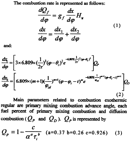
The feature of the non-rated condition different from the rated one is the change of combustion exothermic regular, corresponding to load changing; the fuel supply is changed, so the condition of combustion in cylinder is changed. A double VIBE curves was used for simulating the principle of combustion exothermic regular under the non-rated condition as shown in Fig6. As seen in Fig6, the combustion process was divided the primary mixing combustion process and diffusion combustion process.
The combustion rate is represented as follows:

The combustion advance angle θz is represented by:
θz = θg + Δθ1 + θ2 (4)
Where θg is the designed fuel injection advance angle that is regulated by Variable Injection Timing Unit (VIT) corresponding to the load, which is shown in Fig7.