2.2. Market acceptance
If this new Alfa Laval laboratory method can be accepted by classification societies, engine builders, oil companies etc., the market would have an excellent tool to classify separation equipment and to compare different brands of equipment on equal conditions.
丂
2.3. The new laboratory test method
To avoid all these difficulties, referring to the use of actual HFO or LO, a synthetic oil was selected according to a given specification and with a clearly defined temperature/viscosity relationship. This allows tests to be carried out at exactly the same viscosity as found in the HFO or LO under normal operational conditions.
The synthetic oil used is a standard product on the market that can be replaced by new batches always having the same properties. The particles used are monodisperse plastic particles that are available in a range of sizes and which are produced to very exact dimensions. All particles of the same size group have exactly the same diameter.
Since the density of these plastic spheres is lower than that of typical catalyst fines found in fuel oil or abrasive particles in lube oil, separation would be more difficult for a given particle size, but otherwise the test conditions could very closely approximate the conditions found in normal operation. If wanted, an extrapolation of the test results to higher densities is possible using Stoke's law.
The size of the particles selected for the test method are of 5 and 2.5 micron since these are relevant with respect to the tolerances found in fuel injection and engine lubrication systems and are small enough to show significant differences in performance levels.
Analysis of the particles in the samples before and after the separator tested is carried out using a Malvern Mastersizer. This instrument measures particle size distribution by laser diffraction.
Since only two clearly defined particle sizes are present in the oil during test it was possible to develop our own special computer software for accurate determination of the concentrations of each particle size.
In a typical test, the prepared mixture of synthetic oil and plastic particles is heated to a temperature that gives the same viscosity as a standard grade of HFO or LO has when heated to the recommended separation temperature. The particle suspension is the feed through the separator at different feed rates and samples are taken before and after the separator at fixed time intervals after a discharge.
The method has shown that it can produce consistently reproducible results for a given set of conditions and is therefore considered suitable as a high accuracy test method for the determination of separation efficiency.
丂
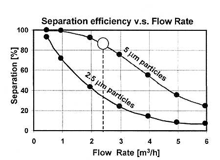
2.4. Separation efficiency curve
Typical data from test results are shown in figure 1. The S-shaped curves are general for all brands of centrifugal separators and not connected to a specific design. The position of the curves in the diagram is dependent on size and design of the separator and on oil viscosity and particle size and density.
Fig. 1 demonstrates clearly the gradual decrease in separation efficiency as the flow rate increases and a distinct difference in separation efficiency between 5 and 2.5 micron particles.
For each combination of separator size, oil type and viscosity grade there is a given recommended capacity set by the separator manufacturer. The test data in figure 1 was done at oil viscosity 35 cSt which corresponds to HFO 380 when heated to 98 C. The recommended capacity is shown by the big white dot in the figure.
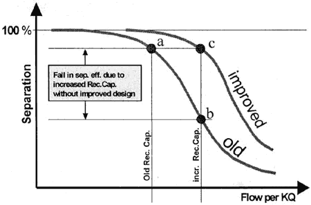
If the recommended flow rate is increased without being justified by a technical improvement it will be at the cost of lower separation efficiency. See figure 2. This is demonstrated in fig. 2 by moving the recommended capacity from point a to point b.
Uncontrolled increase of the recommended flow rate will end up with very low or even no efficiency which means that the separator operates as a very expensive and unnecessary pump.
By technically improving the design of the disc stack in the separator bowl the efficiency curve will move to the right in the diagram. It will then be possible to increase the recommended capacity and still maintain the efficiency level. This is shown in figure 2. The new improved efficiency curve can be given a higher recommended capacity at the same efficiency level as the old curve.
丂