When the valve opening is completed, the open side electromagnetic spool valve is released, and the open side logic valve is closed. At the valve closing timing, the close side electromagnetic spool valve is operated, the close side logic valve is opened, the hydraulic pressure is relieved, and the exhaust valve is closed with the pressure of the air piston.
In the exhaust valve system of the conventional “cam+hydraulic drive” type for the test engine, the valve opening speed is generally 1.8 m/s, the working hydraulic pressure is around 15 MPa, and the piston diameter is 44 mm. For the new system, the piston diameter of 40mm is required to obtain two times of the valve opening speed than the conventional system. Table 4 shows the principal particulars of the exhaust valve system.


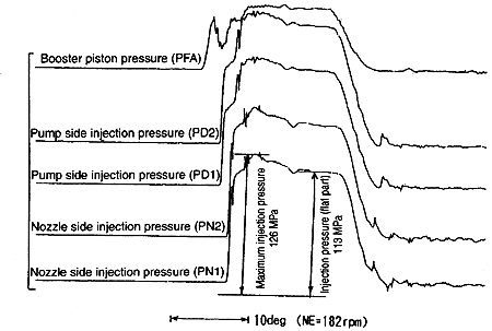
Fig. 9 Measured date of injection system
3.2.2 Performance evaluation by single system test
(1) Fuel injection system
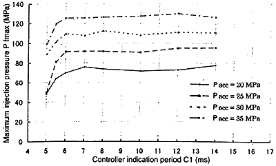
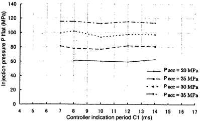
The test is carried out by changing the accumulation pressure Pacc to 20, 25, 30 and 35 MPa, and changing the operational time of the electromagnetic spool valve (the controller indication time : C1), respectively. Fig. 9 shows the measured data at the rated point. The maximum injection pressure on the nozzle side is 126 MPa, the pressure at the flat part is 113 MPa, the injection period is 18.2 deg., obtaining excellent injection mode which is close to the rectangular shape. The working fluid system shows no steep pressure fluctuation to suspect the generation of the cavitation. Fig. 10 shows the change in injection pressure with the accumulating pressure as parameter. When the accumulating pressure Pacc equals 35MPa, the maximum injection pressure of 135 MPa and the pressure at the flat part of approximately 120 MPa are obtained achieving the target.
Maximum injection pressure (plunger diameter: φ 26 mm)

Injection pressure flat (plunger diameter: φ 26 mm)

Fig. 10 Controller indication period and injection pressure
(2) Exhaust valve system
Fig. 11 shows the measured data of the exhaust valve system. The lift of the exhaust valve shows that the valve is opened/closed at high speed, and the speed just before the seating is successfully dropped when the valve is closed. Fig. 12 shows the relationship between the accumulating pressure and the valve opening speed with the air spring pressure as the parameter. The targeted valve opening speed of 3 m/s can be achieved at Pacc of 35 MPa and the air spring pressure of 0.7 MPa.
3.3 Performance evaluation test with single cylinder test engine
(1) Effect of exhaust valve opening timing The condition to optimize the fuel consumption at the load of 100%, 75% and 50% is examined by changing the exhaust valve opening timing.
BACK CONTENTS NEXT