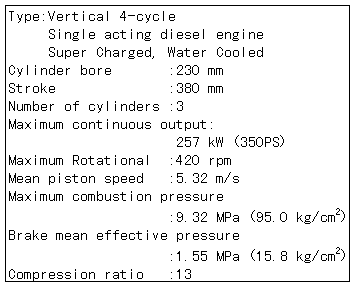
Though the engine is manufactured with the specification of using MDF, its fuel system is remodeled so as to heat the fuel to realize the operation with MFO. Also, in order to examine the combustion characteristic and the fuel injection characteristic, detectors for the in-cylinder pressure, the fuel injection pressure and the lift of the fuel injection needle valve are mounted thereon.
2.2 Fuel used in test
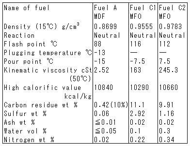
MDF and two kinds of MFO shown in Table 2 were used in the test. Two kinds of MFO were selected taking into consideration the nitrogen content and the sulfur content in the fuel. That is, MFO of the fuel C2 contains more nitrogen, and less sulfur compared with the fuel C1. This fuel was selected to examine whether N2O is influenced by the nitrogen or sulfur in the fuel.
Table 1 Principal particulars of test engine

2.3 SCR system
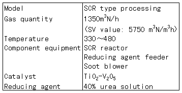
The SCR system used in the test is of Selective Catalytic Reduction type with TiO2-V2O5 for the catalyst and with 40% urea solution for the reducing agent, and its principal particulars are shown in Table 3. The typical reaction formula with this SCR system is as follows.
(NH2)2CO + H2O → 2NH3 + CO2
NO + NH3 + 1/4O2 → N2 + 3/2H2O
NO + NO2 + 2NH3 → 2N2 + 3H2O
The contour of the reactor of the SCR system and the system diagram of the denitriding system are shown in Figs. 1 and 2. In the reactor, two catalyst layers comprising nine catalysts (40 cells) of 150 mm x 150 mm in section and 580 mm in length are arranged, and the reactor is installed at approximately 14m downstream of the engine outlet. The piping from the engine outlet to the reactor is heat-insulated in order to prevent the exhaust gas temperature from being dropped. The reducing agent is injected from the nozzle provided at approximately 2 m upstream of the reactor, and mixed, and further mixed at the bent pipe part, and led to the reactor. The pouring quantity of the reducing agent was calculated in advance so that the denitriding ratio is 90% at each load of the diesel engine, and manually set to the value.
Table 2 Properties of test fuel

Table 3 Principal particulars of SCR

2.4 Measuring instrument
The measured composition of the exhaust gas and the kinds of the instruments are shown in Table 4.
2.5 Test method
The diesel engine was run at the 50% load and 75% load of the maxium continuous output with a propeller law using three kinds of fuel, the characteristics of the diesel engine and the concentration of NOx, O2, CO2, CO, HC and N2O in the exhaust gas from the engine outlet were measured, and the effect of the fuel property on the harmful exhaust emissions such as N2O was examined. The temperature of the fuel was set to be approximately 1000℃ at the inlet of the fuel pump in a case of MFO.
BACK CONTENTS NEXT