Fig. 2 A schematic model used for analyzing propeller motion.
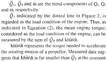
The model is expressed using an equation of motion which takes the forms shown below in Equation (1).

where
Qe = Torque transmitted from shaft to propeller (Nm)
Qp = Propeller torque generated by the hydrodynamic
force on propeller blades (Nm)
I = Moment of inertia of propeller in sea water (kgm2)
ω = Angular rotational speed of propeller (rad/s)
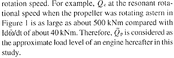
As shown in Figure 2, Qe varies over time both in terms of magnitude and frequency as rotational speed increases because it includes vibratory elements. Qp can be considered to depend on rotation speed only and increases as rotational speed increases. Since the rotational speed of the propeller varies so slowly as seen from Figure 1, fluctuations of high frequency in Qp may be negligible. In order to consider the load condition of the engine, all high frequency elements resulting from torsional vibration on both sides of Equation (1) were filtered out. The resulting equation containing only trend components may thus be written as

where


Harmonic torque elements of an engine can be expressed as a function of mean indicated pressure as follows4.
hi = ai + bipm (3)
where
pm is mean indicated pressure.
ai, and bi are positive coefficients corresponding to the orders of the harmonic torque elements.
The rate of increase of h, was compared with that of pm when pm increased by Δp as follows:

Equation (4) shows that the rate of increase in harmonic torque components is smaller than that of mean indicated pressure. Therefore, using the rate of increase in mean indicated pressure as the rate of increase in harmonic torque elements would lead to a conservative result in estimating torsional vibratory torque. Thus, the rate of increase in mean indicated pressure, which is also regarded as the load condition of an engine, is used as the rate of increase in the harmonic torque elements hereafter in this study.
The various symbols used in this paper and illustrated in Figure 3 are defined below in order to clarify their respective meaning.
Fig. 3 Schematic illustration showing propeller torque when rotating ahead and astern.
QSmax = peak torque in steady ahead condition
QTmax = peak torque in crash astern condition
QVS = amplitude of torsional vibration torque in steady ahead condition
QVT = amplitude of torsional vibration torque in crash astern condition