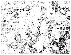
Photo 3 Micro Structure of Diffusion-Bonded Area
The durability of diffusion-bonded piston was well-proved through the accelerated hydraulic fatigue test and thereafter through the endurance test of the prototype. The piston was cut and inspected after the endurance test of the prototype. Neither cracks nor corrosion was observed around the diffusion-bonded sections.
The piston skirt of a floating type is made of nodular cast iron. The skirt profile is well-designed through 3-D FEM analysis so that the excessively high surface pressure is not loaded on the ceramic layer of the cylinder liner described later when a side force is loaded.
The piston is provided with one oil-scraper ring and three compression rings coated with wear-resistant ceramic. This ring set yields the specific lub. oil consumption of 1g/kWh.
3.4 Cylinder Liner and Piston Rings
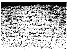
The conventional materials and surface treatments have limited the mean piston speed to 8-10m/s. Instead of these, a newly developed wear-resistant ceramic is coated on the sliding surfaces of both cylinder liner and piston rings by the method of low-pressure plasma spray. [2] The coated layer is shown in Photo 4 and its thickness is 0.5mm after finish-grinding and honing. The spray powder is a composite of harmonium oxide and molybdenum for the top coat, and a mixture of molybdenum and other metal components for the bond coat. The composition and the grain size of spray powder are optimized so that high strength is obtained without losing the excellent wear-resistance.

Photo 4 Wear-Resistant Ceramic Layer
The ceramic layer is extremely wear-resistant in comparison with cast iron used in the conventional engines. The comparison test, which was carried out with Mitsui 12V42M (6,000kW x 514rpm), shows that the wear amount of ceramic layers is 1/8 to 1/4 as compared with cast iron. [3] This allows the piston speed to be increased up to 12m/s while ensuring the long service life.
The wear rate of ceramic layers was measured on 6ADD30V for the 3.1MW power plant after 8,000 operating hours, i.e. 0.007mm/1,000h in diameter for the cylinder liner and 0.020mm/1,000h in radius for the top piston ring. Neither cracks nor separation was observed on the ceramic layers.
3.5 Cylinder Cover and Gas Exchanging Valves
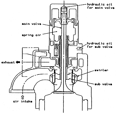
The unique single valve gas exchanging system shown in Fig.6 has been developed in order to enlarge the aerodynamic area of the valves greatly, in place of the conventional four valve system with two intake and exhaust valves respectively. This system reduces pressure losses during the gas exchanging period, which results in higher thermal efficiency even under the high B.M.E.P. as well as the high piston speed.

Fig. 6 Single Valve Gas Exchanging System
BACK CONTENTS NEXT