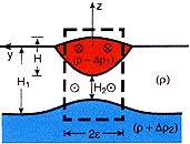
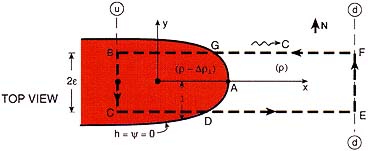
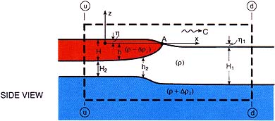
Fig. 3b.Ѓ@A cross-section of the modeled pool (top panel), a top view (central panel) and a side view of the pool (lower panel). The associated control volume is shown with the dashed line. The length of the control box is a few deformation radii and the width is 2ѓГ. The thicknesses H, H1 and H2 correspond to the pool upstream, the intermediate water downstream and the intermediate water upstream. All are taken along the equator (i.e., at y ЃЯ 0). Note that the top view (central panel) corresponds to the observations shown in Fig. 1 and the side view (lower panel) to the observed structure shown in Fig. 2. The coordinate system x, y, z is moving with the pool at speed C; the fixed coordinate system xs, ys, zs is not shown.
Ѓ@
FORMULATION
Ѓ@
As an idealized formulation of the problem, consider again the situation shown in Fig. 3. The inviscid intrusion propagates eastward at the (assumed steady) propagation rate C. Downstream at x ЃЁ +Ѓ‡ both the intermediate and the deep fluid are at rest, but in a coordinate system traveling with the pool they appear to be moving toward the intrusion at speed -C. (Note that the terms ЃgupstreamЃhandЃgdownstreamЃhare used in terms of their relationship to the pool.) To compensate for the volume displaced by the advancing pool, the intermediate layer is squeezed underneath the pool and speeds up as it dives under it. The infinitely deep fluid below maintains its uniform speed -C, however.
Using a moving coordinate system the upstream and downstream fields can be connected without solving for the rather complicated region in between. This is described in Nof (1998) and need not be repeated here.