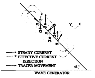
and the tracer movement level. The relation depends on the water depth above the submerged breakwater. The tracer movement level at the points from P1 to P4 is one level larger than that at from P5 to P8.
(2) Direction of Sand Movement
In Figure 10 the dotted line shows the direction of tracer movement and the solid line that of the steady current. The reason why the direction of the steady current does not agree with that of the tracer movement is that the amplitude of the un-steady current component is larger than the steady current velocity on the submerged breakwater.
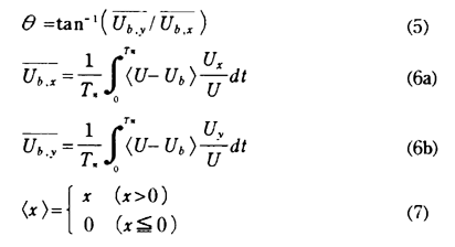
The tracer movement is induced when the wave height becomes larger than the some critical level. The current velocity derived from the critical wave height in small amplitude wave theory is defined as the critical velocity Ub. The discrepancy between the current velocity U and the critical velocity Ub may have large influence to the direction of tracer movement. Therefore, the effective current direction θ can be defined by the following equations.
where, the minimum velocity Ub=10.8cm/s in this case. The broken line in Fig.10 indicates the computed effective current direction θ . The direction θ agrees well with the tracer movement as shown in Fig.10. The direction θ is applicable to estimate approximately the direction of tracer movement.
6. CONCLUSION
In this study, the following results are obtained.
(1) The wave height decreases on the the submerged breakwater by plunging wave breaker. The overtopped incident waves and waves diffracted by the submerged breakwater are composed on the breakwater crown.
(2) The experimental formula for the wave height variation on and at the backward of the submerged breakwater for regular and multi-directional random waves is proposed.
(3) The wave profile on the submerged breakwater can be estimated by the Boussinesq equation model. But the estimated wave height is smaller than measured at the backward of the submerged breakwater. One of the reasons is wave breaking effects in the model.
(4) Strong current is measured at the backward of the submerged breakwater. The irregularity and directionality of incident waves give little influence on the direction and velocity of the steady current. The estimation method for the tracer movement direction is proposed.
REFERENCES
1) Suzuki,Y., T.Hiraishi, H.Tomikashi, Y.Takaba, M.Minami, and Y.Iwagaki (1995) : Field Observation and Experiment on Beach Protection Method, Proc. of Japaneses Coastal Eng. Conf., vol.42, pp. 696-700.
2) Goda,Y. and Y.Suzuki (1975) : Computation of Refraction and Diffraction of Sea Waves with Mitsuyasu's Directional Spectium, Tech. Note of Port and Harbour Res. Inst., No.230, 45p.
3) Madsen,P.E. and O.R.Sorensen (1992): A New Form of Boussinesq Equations with Improved Linear Dispersion Characteristics, Part 2, A Slowly- varying Bathmetry, Jour. of Coastal Eng., Vol.18, pp.183-204.
4) Kawai,H., T.Kudoh, T.Masumoto, I.Uehara, and T.Hiraishi (1996) : Laboratory Simulation on Wave, Current and Sand Movement around Submerged Break-water, Proc. of Japanene Coastal Eng. Conf., vol.43, (in printing).