Fig. 8-2 shows the basic signaling system (R-Y-G). When a train operating at the planned speed confirms the caution signal of signal B, the train reduces its running speed to pass signal B at a speed of 45 km/h or less. Then, the stop signal of signal A causes the train to stop at a position 50 m outside of (in front of) signal A.
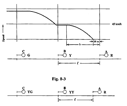
In this case, Fig. 8-3 shows the signaling system when the block section (l) for signal B is shorter than the required braking distance (b) from a speed of 45 km/h such as for dedicated electric railcar lines. Here, signal B displays a speed restriction signal and signal C displays a reduced speed signal.
(4) Braking distance and maximum operating speed
The signaling method is determined by the relationship between the block section length and the braking distance of the train. However, since the signal confirmation distance is set at 600 m for all practical purposes, the braking distance is also limited by this figure. The results of calculating the necessary braking distance assuming a maximum operating speed of from 88 km/h to 70 km/h and a caution signal speed limit of 45 km/h using the formula below are shown in Table 4. An idle running time of eight seconds was used in these calculations (passenger trains: 10 cars, freight trains: approximately 45 cars).