and recorded as De. For diesel exhaust, the maximum exhaust water vapur concentration (in %) expected during testing shall be estimated, under the assumption of a fuel atom hydrogen/carbon (H/C) ratio of 1.8/1, from the undiluted CO2 span gas concetration (A. its measured in 11 2 t above) as follows
Hm=0.9・A (5)
and recorded as Hm.
8.2.2.3 The water quench shall be calculated as follows:
and shall not be greater than 3%
where
De=Expected diluted NO concentration ppm
C=Diluted NO concentration ppm
HM=Maximum water vapour concentrtion %
H=Actual water vapour concentration %
Note: It is important the NO span gas contains minimal NO2 concentration for this check, since absorption of NO2 in water has not been accounted for in the quench calculations
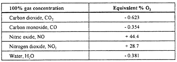
8.3 O2 analyser interference
8.3.1 Instrument response of a PMI analyser caused by gases other that oxygen is comparatively slight The oxygen equivalents of the common exhaust gas constituents other constituents are shown in table5
Table 5. Oxygen equivalents
8.3.2 The observed oxygen concentratios shall be correcteit by tIre following formula ifhigh precision
8.3.3 For ZRDO and ECS analysers instrument interference caused by gases other than oxygen shall be compensated fur in acesirdance ssit)i the instrurrierit supplier's instructions
9 Calibration intervals
The analysers shall be calibrated according to sectros S at least every 3 mirnins or whenever a system repair or change is made that could influence calibration
MEPC 39/6/1
ANNEX
Page 61
APPENDIX 7
CALCULATION OF EXHAUST GAS MASS FLOW
(CARBON BALANCE METHOD)
1 INTRODUCTION
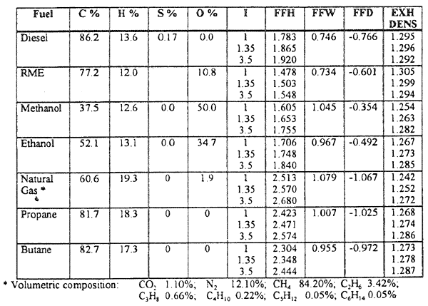
1.1 This appendix addresses the calculation of the exhaust gas mass flow and/or of the combustion air consumption Bulb methods given in the following are based on exhaust gas concentration measurement, and on the knowledge of the fuel consumption. Symbols and descriptions of terms and variables used in the formulae for the carbon balance measurement method are summarized in table 4 of appendix 3
1.2 Thin appendix includes two methods for calculating the exhaust gas mass floss as follows Method I (Carbon balance) is only valid using fuels without oxygen and nitrogen content, and, Method 2 (Universal, carbon/oxygen-balance) is applicable for fuels containing H, C, S, O, N in known composition
1.3 Method 2 provides an easy understandable but universal derivation of all formulae including all constants This method is provided because there are many cases where the present available constants, neglecting essential parameters, may lead to results with avoidable errors Using the formulae within Method 2, it may also be possible to calculate the essential parameters under conditions deviating from standard conditions 1.4 Examples of parameters for sonic selected fuels are offered in table 1. The values for fuel composition are for reference purposes only and shall not be used in place of the composition values of the oil fuel actually used
Table 1. Parameters for some selected fuels (examples)