MEPC 39/6/1
ANNEX
Page 58
7.9 Test interval
The efficiency of the converter shall bc tested prior to each calibration of the NO3
analyser.
7.10 Efficiency requirement
The efficiency of thc converter shall not be less than 90%, but a higher efficiency of
95% is strongly recommended.
Note: If, with the analyser in the most commons range. the NO, converter cannot give a
reduction from 80% to 20% according to 7.2 above, then the highest range whiieh will give
the reduction shall be used.

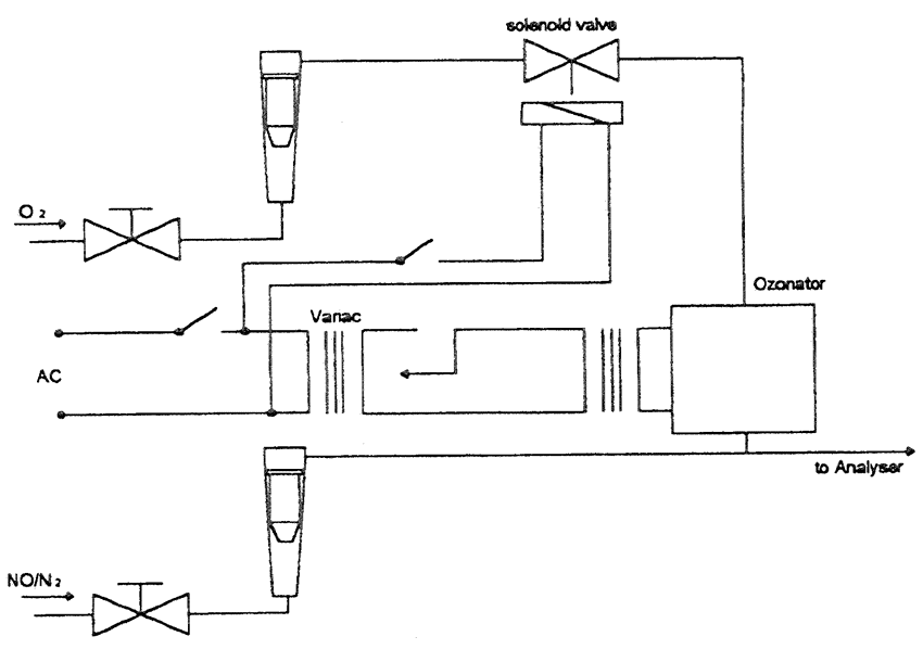
Figure 1. Schematic of NO2 converter efficiency device
8 Interference effects with CO, CO2, NO, and O2 analysers
Gases present in the exhaust other than the one being analysed may interfere with the
reading in several ways. Positive interference may occur in NI)IR and PMI) instruments
where the interfering gas gives the same effect as the gas being measured, but to a lesser
degree. Negative interference may occur in NDIR instruments by the interfering gas
broadening the absorption band of the measured gas. and in CLD instruments by the
interfering gas quenching the radiation. The interference cheeks in 8.1 and 8.2 below
shall be performed prior to an annalyser's initial use and after major service intervals.
8.1 CO analyser interference check
Water and CO2 may interfere with the CO analyser performance. Therefore, a CO2 span gas
having a concentration oaf 811 tin 11)01/of full scale of the maximum operating range used
during testing shall be bubbled through water at room temperature and the analyser
response recorded. The analyser shall not
MEPC 3916/I
ANNEX
Page 59
be more than 1% of full scale for ranges greater than or equal to 300 ppm or more than
3 ppm for rangesbelow 300 ppm.
8.2 NOx analyser quench checks
The two gases of concern for CLD (and HCLD) analysers are CO, and water vapour. Quench
responses to these gases are proportional to their concentrations, and therefore require
test techniques to determine the quench at the highest expected concentrations experienced
during testing.
8.2.1 CO2 quench cheek
8.2.1.1 A C02 span gas having a concentration of 80 to 100% of full scale of the
maximum operating range shall be passed through the NDIR analyser and the CO2 value
recorded an A. It shall then be diluted approximately 50% with NO) span gas and passed
through the NDIR and (H)CLD. with the CO2 and NO values recorded as B and C, respectively.
The CO2 shall then be shut off and only the NO span gas shall be passed through the
(H)CL.D and the NO) value recorded as D.
8.2.1.2 The quench shall be calculated as follows:

and shall not be greater than 3% of full scale.
where:
A = Undiluted CO2 concentration measured with NDIR %
B = Diluted CO2, concentration measured with NL)IR
C = Diluted NO concentration measured with (H)CLD ppm
D = Undiluted NO concentration measured with (H)CLD ppm
8.2.1.3 Alternative methods of diluting and quantifying of CO2 and NO span gas values,
such as dynamic mixing/blending. may be used.
8.2.2 Water quench check
8.2.2.1 This cheek applies too wet gas concentration measurements only. The calculation
of water quench shall take into consider dilution of the NO span gas with water vapour and
sealing of water vapour concentration of the mixture to that expected during testing.
8.2.2.2 A NO span gas having a concentration of 80 to 100% of full scale of the normal
operating range shall be passed through the (H)CLD and the NO value recorded at D. The NO
span gas shall then be bubbled through water at room temperature and passed through the
(H)CLD and the NO value recorded as C. The analyser's absolute operating pressure and the
water temperature shall be determined and recorded as E and P. respectively. The mixture's
saturation vapour pressure that corresponds to the bubbler water temperature (F) shall be
determined and recorded as G. The water vapour concentration(in %) of the mixture shall be
calculated as follows:

and recorded as PP. The expected diluted NO span gas (in water vapour) concentration
shall be calculated as follows:

前ページ 目次へ 次ページ