|
2. Offshore Structures
Examples of conceptual designs of Mega-Float and Marine Float, large floating structures, will be described below.
Promotion of Practical Use of Mega-Float
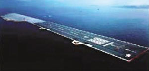
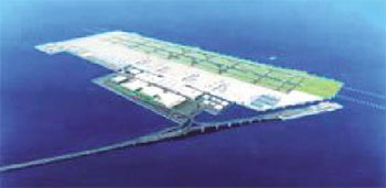
The Mega-Float, which features high resistance to earthquakes and environmental friendliness, embodies the foremost in Japanese technologies. It is the fruit of an R&D project carried out from fiscal 1995 through 2000 to facilitate the development of social overhead capital by effectively utilizing oceanic space. The Study Group on the Utility of Mega-Float Airports and the Conference to Evaluate and Select the Construction Method for the Haneda Airport Re-expansion Project in fiscal 2001 and 2002 arrived at a conclusion that the construction of floating airports was feasible on the basis of the result of a demonstration test using a 1,000-meter long floating airport model. Further, the Demonstration Test on the Function of Mega-Float as Data Handling Center conducted in collaboration with the Ministry of Internal Affairs and Communications, and the Ministry of Economy, Trade and Industry demonstrated that the availability of Mega-Floats as low-cost and high-reliability data handling centers. The MLIT is promoting practical and expanded use of Mega-Floats, which are planned for utilization as port facilities including container terminals, energy supply bases and leisure facilities in addition to the already proposed purposes including airport and data backup centers.
1,000-meter Long Floating Airport Model
(from the MLIT's website)
Examples of Conceptual Designs of Marine Float
(this section has been provided by courtesy of The Floating Structures Association of Japan)
Large Floating System for Oceanic Wind Power Generation
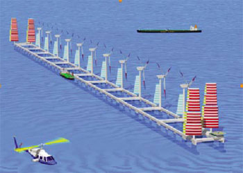
The Floating Structures Association of Japan is engaged in a research project to develop a sail-rigged, large floating system for oceanic wind power generation under commission from the National Institute for Environmental Studies. Features of the system under study include production of hydrogen by electrolysis of seawater with the generated electric power; self-positioning in a prescribed range with sails instead of using conventional mooring equipment; the use of thrusters as required in stormy weather to shift to safe waters; drifting-free position kept with small power by utilizing lifts working on the struts of the floating body; slender semi-submersible and raft-like shape of the floating body; light weight and flexible structure; and secured long durability under appropriate maintenance.
|
Conceptual Drawing of Large Floating System for Oceanic Wind Power Generation
|
Main Specifications:
Type of Structure: Slender semi-submersible
Dimensions: 2,060 m (L) x 70.2 m (B) x 30 m (D)
Displacement: About 200,000 tons
Max. Speed: 8 knots
Equipment: Wind Power Generator 5 MW x 11 sets
Hydrogen Plant x 1 set
Sails, 4,500 m2 x 4 sets
Thruster, 4,200 kW x 6 sets
Offshore LNG Terminal
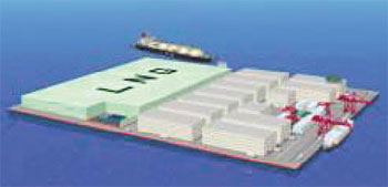
The Floating Structures Association of Japan is proposing an offshore LNG terminal using a huge floating body Mega-Float. Its remarkable functions and features include remarkable safety; LNG storage capability in an isolated offshore space; multipurpose use of the vast top face of the floating structure and internal space as well as its tremendous storage capacity; no emission of cold heat resulting from a complex combination of functions, and utilization of cold heat by cold heat electricity generation and freezing warehouses.
Conceptual Drawing of Offshore LNG Terminal
Main Specifications:
Design Conditions:
Wind: 23 m/s
Wave: 4.5 m
LNG storage: 1,000,000 tons
Power generation: 1,000 kW
Chilled food storage: 500,000 tons (500,000 m2) (-40 to 60℃)
Dimensions: 600 m (L) x 500 m (B) x 38/10 m D x 8 m (d)
Mooring System: Anchor/chain mooring (16 lines)
Floating Container Terminal Compatible with Very Deep Water
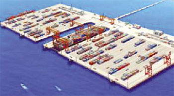
This terminal features cargo handling on both sides, made possible by the use of dock-type berths; lines of smooth flow secured by the use of shift-able opening/closing gates for trucks carrying containers; cargo handling capacity four times as large as that of conventional single-side cranes, achieved by the use of portal cranes, which can be shared by both right and left docks, moved by shifting bogies; automatic berthing, unberthing and mooring made possible by the installation of a ship berthing support system; internal space of the floating body utilizable as a container yard or for other purposes; and phased expansion facilitated by the flexibility of the floating body.
|
Conceptual Drawing of Floating Container Terminal Compatible with Very Deep Water
|
Main Specifications:
Type and size of structure: Steel pontoon, 1,310 m (L) x 600 m (B)
Deck area: About 73 ha
Facilities for two dock-shaped berths
Gantry-type container crane: Six sets (three sets per berth)
Movable gate: Two sets (one set per berth)
Automated mooring system: Two sets (one set per berth)
Platform car: Two sets
Umihotaru Airport
The Floating Structures Association of Japan proposes a hybrid- structured Umihotaru (vergula hilgendorfi, or light-emitting plankton) airport, which can make use of the Tokyo Bay Aqua- Line to meet the expected growth in demand for air transport service in the greater metropolitan zone. It will be built by a combination of floating body construction and land reclamation. The Umihotaru Airport will be used by both domestic and international flights around the clock, and feature diverse functions, high accessibility, adequate consideration for safety and security, little environmental impacts both during construction and after completion, short construction period, and low cost.
Conceptual Drawing of Umihotaru Airport
Floating Multipurpose Offshore Base
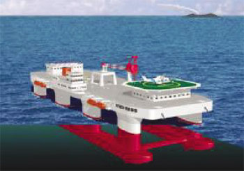
The Floating Structures Association of Japan has proposed the architectural design of a network system intended for investigation, development and conservation of Japan's exclusive economic zone (EEZ) and the development of remote islands, and is studying floating multipurpose offshore bases which would be needed for these activities. Regarding their purpose and features, the association's proposal envisions the establishment of seven floating offshore bases in the EEZ, and the utilization of these bases as relay points for helicopter service linking the mainland and major remote islands to facilitate rescue activities; to meet private sector needs for rapid transport of passengers and cargo; as facilities for atmospheric, meteorological and oceanographic research activities; and the exploration of natural resources and offshore experiments and studies. Each of these offshore bases will be a relatively oscillation-free, semisubmersible floating body with a large deck space.
|
Conceptual Drawing of Floating Multipurpose Offshore Base
|
Main Specifications:
Design Conditions:
Wind: 50 m/s
Wave: 12 m
Type of Structure: Slender Semi-submersible
Dimensions: 162 m (L) x 50 m (B) x 31 m (D) x 14 m (d)
Displacement: About 21,000 tons
Complement: 75 persons
Max. Speed: 8 knots
Equipment: Thruster, 2,500 kW x 6 sets
Helicopter Deck x 1 set
Deck Crane x 1 set
|
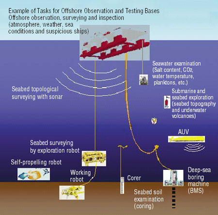
Conceptual Drawing of Offshore Observation and Testing Base
|
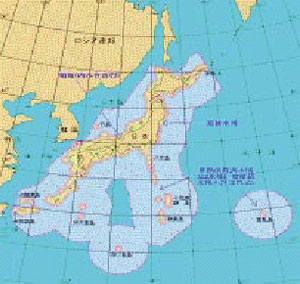
Japan's EEZ
3. Ship Machinery Industry Ballast Water Treatment Technology
A ship's ballast water picks up small organisms, their eggs and larvae living in the port or harbor from where the water was loaded. They hitchhike on the ship, which carries them to foreign environments, and immigrate into the waters of the ship's ports of call where the ballast water is discharged. Over four billion tons of ballast water is estimated to be carried a year around the globe. Many cases are reported of cross-border immigration of organisms carried by ballast water which affect the ecosystems of the coastal waters into which they are discharged and, through them, human health.
To address these problems, the International Maritime Organization (IMO) in February 2004 adopted the International Convention for the Control and Management of Ship's Ballast Water and Sediments. Under the convention, it will become compulsory, in a phased plan beginning with newly built vessels (each with a ballast tank capacity of less than 5,000 m3) to discharge their ballast water outboard only after treating the water to reduce its microorganism content to the permissible limit.
With a view of successfully implementing the convention, the Marine Environment Protection Committee (MEPC) of the IMO is now studying various guidelines.
Regulation of ballast water, though involving many pending problems, is geared to making it compulsory to reduce the number of organisms in discharged ballast water to a prescribed limit, and to meet this requirement, techniques for the treatment of ballast water are being developed in many countries.
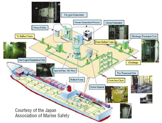
A technique for the treatment of ballast water means a way to kill or remove unspecified organisms distributed in the sea areas where ballast water is picked up. Such techniques now being developed include many different methods, such as filtering and centrifugal separation, mechanical killing, heat treatment, electrochemical treatment and combinations of some or more of these approaches.
In 2006, the “special pipe-treatment system” developed by the Japan Association of Marine Safety, and the “oxidation and electrolytic treatment system” proposed by Sweden were basically approved by the IMO, and four systems including German and Korean techniques, which had been basically approved in 2005, are now expected to obtain final approval through on-board tests and other procedures.
“Special Pipe Treatment System”
Developed by the Japan Association of Marine Safety
|