|
MANOEUVRING PREDICTION OF FISHING VESSELS
Yasuo Yoshimura (Graduate School of Fisheries Sciences, Hokkaido University, Japan)
Ning Ma (National Research Institute of Fisheries Engineering, Fisheries Research Agency, Japan)
Abstract: Fishing vessels generally have good performance in ship manoeuvrability. The relatively large rudder and propeller assist to make such performance, so there has been little need to the manoeuvering prediction. However, the manoeuvring prediction has become very important because the strong rudder force sometimes causes the capsizing accident. As for the principal dimensions of fishing vessels, they are different from conventional merchant ships. The ship length is generally small. The length beam ratio: L/B becomes less than 3.0 particularly in Northern Europe. Besides, they have large initial trim by the stern. Therefore, the hydrodynamic force becomes quite complicated. This makes a difficulty when predicting the manoeuvrability of these vessels.
In this paper, the authors show the database of hydrodynamic derivatives with several fishing vessels including the recent European wide beam vessel, and then introduce the empirical formulas to predict the hydrodynamic derivatives as well as other hydrodynamic coefficients based on the obtained database. Using these empirical methods, manoeuvring ship motions can be easily simulated and the manoeuvring prediction successfully done.
1. INTRODUCTION
Fishing vessels have a relatively large rudder propeller and initial trim by the stern. These arrangements generally make good performance in ship manoeuvrability. However, the manoeuvring prediction becomes very important because the strong rudder force sometimes causes the capsizing accident [1]. Such kind of prediction is also necessary when calculating the broaching motion in following seas [2].
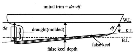
As for the principal dimensions of fishing vessels, the length beam ratio: L/B is rather smaller than the conventional merchant ships. Particularly in Northern Europe, ship length tends to be small. Some of them have less than 3 of L/B. In addition, fishing vessels have a large initial trim by the stern and a false keel as shown in Fig.1. Initial trim becomes 30 or 40% of mean draught of ship. Some false keels also have a trim. Therefore, the hydrodynamic force during manoeuvring becomes more complicated in the manoeuvring prediction of fishing vessels.
Fig.1 Initial trim and false keel of a fishing boat
2. MATHEMATICAL MODEL FOR MANOEUVRING PREDICTION
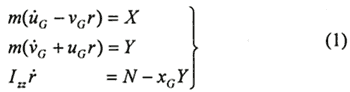
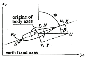
The mathematical model for manoeuvring motion can be described by the following equations of motion, using the coordinate system in Fig. 2.
where, m: mass of ship
Izz: moment of inertia of ship in yaw motion
Fig.2 Co-ordinate system
The notation of UG, VG and r are velocity components at center of gravity of ship (C.G), and XG represents the location of the C.G. in x-axis direction. X, Y and N represent the hydrodynamic forces and moment acting on the mid-ship of hull.
These forces can be described separating into the following components from the viewpoint of the physical meaning.
where, the subscripts H, P and R refer to hull, propeller and rudder respectively according to the concept of MMG [3], [4].
2.1 Forces and Moment Acting on Hull
XH, YH and NH are approximated by the following polynomials of β and r'. The coefficients of the polynomials are called hydrodynamic derivatives.
where, mx, my and Jzz are the added mass and moment of inertia. Drift angle: β and dimensionless turning rate: r' are expressed as β = -sin-1 (v/U), r' = r(L/U).
The notations of u and v are velocity components and U is the resultant velocity at the mid-ship
2.2 Force and Moment Induced by Propeller and Rudder
XP, YP, NP and XR, YR, NR are expressed as the following formulas.
where, δ is rudder angle, XR represents the location of rudder (=-L/2), and tp, tR, αH, and xH are the interactive force coefficients among hull, propeller and rudder. KT is the thrust coefficient of a propeller force. These are the functions of the advance constant of propeller. FN is rudder normal force and described as the following.
where, AR is rudder area. fa is the graduent of the lift coefficient of ruder, and can be approximated as the function of rudder aspect ratio Λ.
fa = 6.13A/(2.25 + Λ) (7)
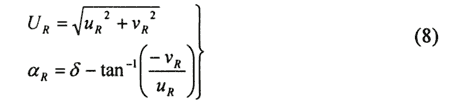
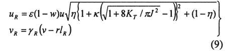
UR and αR represent the rudder inflow velocity and angle respectively, they can be described as the followings.
Where,
ε, K, γR and lR in the above equations are the parameters with the ruder inflow velocity and angle. (1-w) and η are the effective propeller wake fraction and the ratio of propeller by rudder height (Dp/H).
Table 1 Principal particulars of ship models (Full-scale expression)
| Ship Model scale |
A 1/14.6 |
B 1/14.6 |
C 1/14.6 |
D 1/12.2 |
E 1/15.0 |
F 1/16.4 |
| Lpp (=L, m) |
27.50 |
33.74 |
33.74 |
26.85 |
31.00 |
26.16 |
| B (m) |
6.50 |
6.50 |
7.80 |
5.90 |
7:40 |
10.00 |
| d (m, molded) |
2.60 |
2.60 |
2.60 |
2.184 |
2.515 |
4.071 |
| Keel depth (m) |
0.30 |
0.30 |
0.30 |
0.50 |
0.44 |
0.50 |
| dem (m) |
2.90 |
2.90 |
2.90 |
2.684 |
2.955 |
4.571 |
| Baseline trim (m) |
0 |
0 |
0 |
1.724 |
2.37 |
1.000 |
| Initial trim (m) |
0.80 |
0.80 |
0.80 |
0.70 |
0.80 |
0.80 |
| Keel trim (m) |
0.20 |
0.20 |
0.20 |
0 |
0 |
0 |
| Total trim (m) |
1.00 |
1.00 |
1.00 |
2.424 |
3.170 |
1.800 |
| ▽ (m3) |
313.3 |
419.2 |
435.3 |
274.4 |
414.3 |
681.9 |
| Dp (m) |
1.9 |
1.9 |
1.9 |
2.07 |
2.7 |
2.04 |
| L/B |
4.231 |
5.191 |
4.326 |
4.551 |
4.189 |
2.616 |
| dem/B |
0.446 |
0.446 |
0.372 |
0.455 |
0.399 |
0.457 |
| Cb (by dem) |
0.604 |
0.659 |
0.570 |
0.645 |
0.611 |
0.655 |
| Cb/(L/B) |
0.143 |
0.127 |
0.132 |
0.142 |
0.146 |
0.250 |
| Total trim/dem |
0.345 |
0.345 |
0.345 |
0.940 |
1.073 |
0.383 |
| xG/Lpp (%L) |
-2.15 |
-1.48 |
-1.60 |
-10.24 |
-8.71 |
-2.19 |
| AR/Ldem |
1/28.6 |
1/35.0 |
1/37.9 |
1/24.1 |
1/24.6 |
1/27.3(F) |
| Dp/H |
0.904 |
0.904 |
0.904 |
0.955 |
0.971 |
0.838 |
|
|