|
5. FLOW FIELD PREDICTION
Not only the forces and moments are predicted by the computations but also the entire turbulent flow around the ship. In particular the velocity field, showing vortex generation and shedding, the pressure on the hull and the skin friction, showing flow separation, can be very helpful in order to understand the complicated flow phenomena which occur when the ship leaves the straight ahead motion.
Fig. 5 shows some selected flow features at the hull of the RoRo ship turning to star-board with constant yaw rate r'= 0.4 with-out any drift angle. The pressure has been depicted on the hull. Red and blue indicate high and low pressure areas respectively. Due to the asymmetric flow, the stagnation point has moved to the starboard side of the bulbous bow. The transverse velocity field in a cross section shows a pronounced vortex generation and 3D flow separation on the port side of the fore body. On the rear part of the hull the flow meets the ship coming from port. This yields high pressure areas at the port side of the central skeg and rudders and very low pressures at the bottom of the skeg. The steady pure yaw motion does certainly not represent a realistic situation for a manoeuvring ship, but it is thought to be adequate for validation purposes. The flow around a ship in steady oblique flow has been compared with measurements by the authors in other publications, e.g. [1].
In order to get experimental data to verify the predicted flow around a steady turning ship, Particle Image Velocimetry (PIV) has been used to measure the transverse velocities at selected cross sections in the fore body of the RoRo ship model. The measurements were performed at HSVA by Kallweit and Dues from ILA Ltd. See [4] for details concerning the measuring technique. We are not aware of other PIV measurements performed at a turning model in a body-fixed frame. The performed measurements have to be seen as a first attempt to get extensive flow data for validation purposes.
Previous PIV measurements with ship models have mostly been performed at a fixed place at the side of the towing tank, towing the model steadily across the measuring plane perpendicular to the tank's axis. Disregarding the region close to the hull, the transverse velocity components to be measured are larger than the axial velocity in this case. An exception represents the work of Gui et al. [3] where PIV measurements have been performed in a ship-fixed frame for a model in steady oblique motion. In this work, the velocity components were measured in vertical and horizontal longitudinal cuts to avoid excessive parallax errors due to the large axial velocity present in the measured flow. The velocity field in a cross section corresponding to the propeller plane was interpolated afterwards.
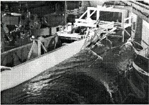
Figure 6: |
PIV measurements at a turning RoRo ship model towed by the CPMC |
In order to get the transverse velocity field in several cross sections in affordable time we had to take a loss in accuracy opting for transverse cuts in the present study. The consequences are larger parallax errors, due to a deviation from orthogonality when focussing the video camera onto the laser light sheet, and larger perspective errors, see for instance [5]. Both errors are related to a certain amount of the out-of-plane velocity component which mixes into the transverse velocity field to be measured. The errors can be reduced increasing the distance of the camera to the laser light sheet and/or reducing the frame of view. Unfortunately, both measures can only be taken to a limited extent. During these first PIV measurements we had to find a compromise between the required accuracy of the experimental results and the effort demands. The measurements in two cross section were performed within 3 days. The acquired data is supposed to be good enough for a qualitative validation of the computed results.
The ship model was rigidly attached to the CPMC and the PIV system was mounted on the model and remotely controlled from the towing tank carriage. Fig. 6 shows the experimental set-up. Different cross sections were measured by shifting the PIV system along an aluminium frame mounted on the fore body of the model. A pulsed laser with 120 mJ/pulse and an underwater digital video camera with 1280×l024 pixel resolution have been used. The laser light beams were directed into the water by mirrors stretching a light sheet in the desired cross section of the model. The video camera, placed about one meter downstream of this position, recorded double-illuminations with a repetition rate of 4 Hz. A sophisticated software identifies the fluid particle in both illuminations (taken within a very short time interval) and calculates the velocities from the determined displacements of the particles from one illumination to the other, [4].
Figure 7: |
Partial view of the model's trajectory along the towing tank |
During each run four arcs of a steady turning circle were performed, Fig. 7. The model speed along track was always 1.80 m/s and the non-dimensional yaw rate r'=0.4. The duration of the steady phases was about 10 seconds, enabling about 40 double-illuminations during each turning circle arc. The velocity field was obtained averaging the corresponding values and putting together several measured frames of view in order to cover the desired domain of the cross section considered.
All features of the flow previously found in the computed results were confirmed - at least qualitatively - by the experiments. The transverse velocities in the cross sections 16 and 18 are compared in Figs. 8 and 9 respectively. The predicted vortical structure can clearly be seen in the measured data. Moreover, the 3D flow separation occurring at the bottom of both frames can also be discerned there, although the region close to the wall could not be captured well during the experiments. There is certainly more work needed to understand if the somewhat different locations and strengths of the computed and measured vortices are due to the experimental errors mentioned above or to errors of the numerical results due to grid resolution, turbulence model, etc. Note that the wall functions used for all computations in this work most probably have deteriorated the quality of the CFD predictions.
Figure 8: |
RoRo ship in steady turn with r'=0.4 and Fn=0.20. Comparison of computed transverse velocities with preliminary PIV data in cross section 16. |
Figure 9: |
RoRo ship in steady turn with r'= 0.4 and Fn = 0.20. Comparison of computed transverse velocities with preliminary PIV data in cross section 18. |
6. CONCLUDING REMARKS
The prediction of hydrodynamic forces and moments acting on the hull of a manoeuvring ship and the viscous flow around it is by far not completely validated yet. This work represents a small contribution in this regard. Results for steady basic motions like oblique motion and steady turning motion are in general satisfactory, but even in these simple cases some doubts remain. For instance, it is not clear yet if the free surface has by all means to be taken into account during the simulations in order to get accurate predictions. CFD can certainly help to understand the complicated flow features occurring at a manoeuvring ship and can yield hydrodynamic forces for comparison purposes. Computations including the free surface and more measurements are absolutely necessary to shed more light on the quality which can be achieved by the numerical predictions.
ACKNOWLEDGEMENT
This work was supported by the German Ministry of Education and Research.
References
[1] Cura Hochbaum A. (1998), "Computation of the Turbulent Flow Around a Ship Model in Steady Turn and in Steady Oblique Motion" , 22nd ONR Symp. on Naval Hydrodyn., Washington D.C., USA
[2] Cura Hochbaum A. and Vogt M. (2002), "Towards the Simulation of Seakeeping and Manoeuvring based on the Computation of the Free Surface Viscous Ship Flow", 24th ONR Symp. on Naval Hydrodyn., Fukuoka, Japan
[3] Gui L., Longo J. and Stern F. (2001), " Towing tank PIV measurement system, data and uncertainty assessment for DTMB Model 5512" , Experiments in Fluids, Volume 31, pp. 336-346
[4] Kallweit S. and Dues M. (2003), "Secondary Flow around a Manoeuvring Ship Model in a Towing Tank" , 5th Int . Symp. on PIV, Busan, Korea
[5] Raffel M., Willert C, and Kompenhans J. (1998), " Particle Image Velocimetry, A Praptical Guide", Springer-Verlag, ISBN 3-540-63683-8
[6] Sussman M., Smereka P. and Osher S. (1994), "A Level Set Approach for Computing Solutions to Incompressible Two-Phase Flow" , Journal of Computational Physics Vol.114
[7] Vogt M. (l998), "A Numerical Investigation of the Level Set Method for Computing Free Surface Waves", Licensiate Thesis at Chalmers University of Technology, Gothenburg, Sweden
[8] Wilcox D.C. (1993), "Turbulence Modeling for CFD" , DCW Industries, La Canada, California, USA
|