|
THE PREDICITON OF HYDRODYNAMIC FORCES ACTING ON SHIP HULL UNDERGOING LATERAL BERTHING MANEUVER IN SHALLOW WATER
Yun-Sok LEE (Kobe University of Mercantile Marine, Japan)
Yasuyuki TODA (Osaka University, Japan)
Hiroyuki SADAKANE (Kobe University of Mercantile Marine, Japan)
Abstract: To evaluate the unsteady motion in undergoing lateral berthing maneuver, it is necessary to grasp very clearly the magnitude and properties of the hydrodynamic forces acting on ship hull especially in shallow water. In this study, numerical calculation was made with respect to the hydrodynamic force according to the water depth and acceleration for Wigley model using the CFD technique. Furthermore by comparing the computational result with the experimental result, validity of the CFD method was verified. The numerical solutions not only evaluated the hydrodynamic force with good accuracy, but also captured the features of the flow field around the ship in detail. Modeling was attempted with a view to expressing the transitional lateral force in a state ranging from rest to uniform motion using the concept of the circulation.
1. INTRODUCTION
The berthing maneuver is a specific work in operating a ship keeping allowance strength of the mooring facilities in addition to safety of the vessel itself, and accurate position and control of the vessel are required with the aid of tugboats. Therefore a considerable amount of time and effort is still necessary. One of the reasons accompanying much difficulty in a berthing maneuver is that the magnitude and features of the hydrodynamic force acting on ship hull for water depths and ship types are not grasped adequately.
This study is the basic research to obtain quantitatively the hydrodynamic forces under the lateral motion by use of the CFD technique, and a view to generalizing the obtained hydrodynamic forces that are to be offered for practical use.
In typical berthing motion such as large tanker vessel, the berthing maneuver is usually executed low lateral moving velocity and in the short distance to the berth. But, the considerable force will act on ship hull because the hull is not a streamlined form for moving direction. In that motion, the transitional lateral force is subjected to the position and strength of the separated vortices. Furthermore since the hydrodynamic forces differ greatly according to their kinetic history even at the same velocity, the force cannot be dealt with as steady or quasi-steady condition. Meanwhile with the lateral moving of the berthing ship in front of the berth, influence of water depth remarkably appears owing to the fact that water depth is so shallow. Also, the transitional lateral force appears strongly, and remains for a very long time.
Assumption was made that in accordance with the conventional method, the hydrodynamic force can be simply divided into inertia force and lateral force. Concerning with the inertia force such as added mass, the authors proposed the simplified formulas by which variation of the water depth and difference among the types of ships can be consideredl). With lateral force, one of the authors made proposal with an estimation formula based on the model experiment2). However there remains room for the experimental accuracy and application range to be examined. Meanwhile in case that complicated hydrodynamic force is to be dealt with, not only just estimation of the hydrodynamic force, but also hydrodynamic comprehension concerning the mechanisms of the hydrodynamic force becomes necessary. For the requirement referred to above, there exist limits with the experimental method. Thus it can be affirmed that the CFD method 3-5) making it possible to visually observe the detailed characteristics of the flow field is the optimum.
2. OUTLINE OF NUMERICAL METHOD
The berthing velocity of a large tanker aided by tugboat operation in harbor is usually less than 0.15m/s, and the Froude Number Fn determined by taking the ship breadth is very small values. Based upon these facts, influence of the free surface was neglected on the computation. The motion mode during the lateral moving used for the computation corresponds to CAT (Constant Acceleration Test) starting from rest to constant acceleration, to uniform movement, to constant deceleration, and to stop.
2.1 Govening equation and turbulence model
The governing equations are the continuity and Naiver-Stokes equations for viscous incompressible flow written in the physical domain using Cartesian coordinate fixed on the ship hull. All variables are normalized by means of the breadth B, the reference velocity U∞(the uniform velocity), fluid density ρ , and combination of these factors.
The SGS turbulence model seems to be suitable for the unsteady and complicated flow field with the shedding vortex and relatively rough computational grid. In the present work, the sub-grid scale model adapted taking the eddy viscosity (vt = l/Re + vs) by Smagorinsky and vs is determined by a Takakura's length scale6),7). The non-dimensional equations are transformed into the computational domain in non-orthogonal curvilinear coordinate. A partial transformation is used in which only the independent variables are transformed. Each equation is generally rewritten in the form of the convection/diffusion equation as follow:
The transport equations are discretized using the 12 point finite analytic method8),9). In the finite-analytic scheme, equation is linearlized in each local numerical elements and solving analytically by the method of separation of variables. Euler implicit method is applied to the time derivatives. Pressure-velocity coupling is accomplished using the PISO algorithm10). Therefore hundred times of repetition is required for every trial of the calculation of one-time step, the coefficient of the FA method was renewed every time repetition.
2.2 Computational Grid and Boundary Conditions
The present computational grid is H-type with constant Y planes, generated by solving the Possion equation. Coordinate system and computational grid of Wigley hull is shown in Fig. 1. The origin is at the water surface and mid-ship section. X is the opposite direction for the movement, Y is the ship length direction and Z is directed vertically downward.
Fig. 1 Coordinate system and computational grid.
Fig. 2 Computational grid on the water plane.
Length, and draft are normalized by breadth. So, the length is l0, breadth is l, and draft is 0.625. The computational gird number is 81 × 95 × 35 in directions of x, y, and z in case of the deep water region. In case that H/d is 2.0 and 1.5, computation was conducted by reducing exclusively the Z axis to l9 and 21. Fig. 2 shows the computational gird on the water surface plane.
The boundary condition in computation an example in the shallow water region as follows: the inlet boundary condition (x =-30); u = Uo, v = w = p = O, the outlet boundary condition (x = 30, O extrapolation); ∂u/∂x = ∂v/∂x = ∂w/∂x = ∂p/∂x = O, the side(right and left) boundary condition (y = ± 25);u = Uo , v = w = p = O. Furthermore the boundary condition on the hull surface was approximated with u = v = w = O, ∂p/∂x= dUo/dt . Body hull is located -5≦ y ≦5, -0.5≦x ≦0.5. Non-dimensional acceleration and deceleration for computation is ±1(dUo /dt = ±1). The Reynolds number in computation was designated as 105 considering the Reynolds number of the experiment, and the non-dimensional time interval of 1 step is Δ t = 0.005 (200 steps are equivalent to the non-dimensional time T = 1.0).
3. NUMERICAL RESULTS
3.1 Comparison of the hydrodynamic force on the difference of the water depth
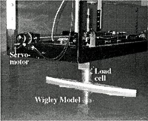
The comparison of the hydrodynamic force between computations and experiments according to the water depth, such as H/d = 2.0, 1.5 and H/d = 7.0 is shown in Fig. 3. The force F and moving velocity Uo in Fig. 3 are normalized values, and the non-dimensional acceleration is 1.0. The solid line gives the computation result, whereas the dotted line gives the experimental result obtained by using a lateral force measurement device. In order to compare both of the hydrodynamic forces directly, inertia force corresponding to the model mass used in the experiment was added to the CFD results. The experimental result in Fig. 3 is obtained by means of lateral force measurement equipment using a servo motor control, as shown in Photo.1. The equipment can run within the 1.0m, and the carriage speed and acceleration are set freely on the personal computer.
Fig. 3 Comparison of hydrodynamic forces.

It is noticed at first that the CFD result is satisfactory enough to coincide with the experimental result. Thus it is validated that the hydrodynamic force obtained from the CFD method can be estimated with sufficient accuracy. Also, the force in Fig. 3 is almost pressure component, and the viscosity stress component is small enough to be ignored. As a feature of the hydrodynamic force caused by the difference of the water depth, especially the transitional lateral force under the uniform movement is showed largely as the force comes to shallower water. Furthermore a feature came to manifest itself remarkably with the decrease of the force in a short time. The added mass concerning the inertia component appearing just after the acceleration and just before the deceleration was found to be almost the same in its magnitude despite the great difference of the flow field around the ship. Also utilizing the merit of CFD computation, change of the flow field dependent on water depth is hereby observed. Instantaneous streamlines of water surface plane in case that H/d=2.0 and 1.5 are shown in Fig. 4, respectively. Since the flow comes to be hard to go through the ship bottom, a flow running around the fore and aft makes remarkable appearance in shallow water. Therefore it is comprehended that great positive pressure is applied onto the front of the hull in a shallow region. To investigate the features of the transitional three-dimensional vortex structure around the ship body, the iso-surfaces of

is shown in Fig. 5. The conditions of vortices are different in the each cross section and time. Consequently, the flow field of ship motion in low-speed lateral motion has the transitional unsteady and three-dimensional vortical nature.
Photo.1 Configuration of Experiment.
From these types of visualized information, the influence on the flow field around the ship hull can very easily be explained. Thus it can be ensured that that the water depth is an important element to affect influence on the hydrodynamic force, and it has become possible to compare and examine the hydrodynamic force in detail based on the CFD computation result.
Fig. 4 |
Instantaneous streamlines of water surface (relative velocity to the hull). |
Fig. 5 Transitional 3D vortex structure around the ship
|