|
MANEUVERING CHARACTERISTICS OF A LARGE CONTAINER SHIP
Sun Young Kim (KRISO, Rep. of Korea)
Yeon Gyu Kim (KRISO, Rep. of Korea)
Nam Sun Son (KRISO, Rep. of Korea)
Seok-Won Lee (Daewoo Shipbuilding & Marine Engineering Co., Ltd. Rep. of Korea)
Kwang-Dong Park (Hanjin Heavy Industries CO. Ltd, Rep. of Korea)
Abstract: Recently the attention to large container ships whose size is comparable with large tankers and speed is very high has been increased due to their increasing demand. As IMO adopted finally IMO maneuvering standards in 2002, it is necessary to investigate the maneuvering performance of these new large container ships. In this paper, the maneuvering characteristics of a large container ship were investigated through model tests and computer simulation. Firstly, the mathematical model for maneuvering motion with 4DOF(four degree of freedom) was established to include effects of roll motion on the maneuvering motion. And to obtain roll-coupling hydrodynamic coefficients of a container ship, 3DOF HPMM system of KRISO were updated to 4DOF HPMM system by adding a roll moment measurement system and a roll motion mechanism. With newly constructed 4DOF HPMM system, HPMM tests were carried out for a 9000TEU container ship at full load and ballast conditions. Using the hydrodynamic coefficients obtained, simulations were made to predict the manoeuvring motion. Free running tests were also carried out to validate the mathematical model and simulation results. In this paper, maneuvering characteristics of a large container ship is discussed based on the experimental and simulation study of a 9000TEU container ship. The effects of roll motion and draft condition on the maneuvering performance is also discussed.
1. INTRODUCTION
International Maritime Organization (IMO) finally adopted the resolution MSC136(76) on standards for ship maneuverability in 2002 after two years' activity of review and revision of interim maneuvering standards[1]. This resolution shall be applied to ships of all rudder and propulsion types, of 100m in length and over, and chemical tankers and gas carriers regardless of the length, constructed on or after 1 January 2004.
Since IMO adopted interim maneuvering standards in 1993[2], there have been many studies on predicting manoeuvring performance of a ship at the design stage. Most studies have focused mainly on large tankers which have relatively poor maneuvering performance and more chances to fail to satisfy the IMO maneuvering standards than other ships. For container ships, there have been little difficulties in satisfying IMO manoeuvring standards because container ships generally have a good maneuvering performance due to her high slenderness. However, the size and speed of container ships have recently been increased very rapidly. 8000TEU container ships have already been operating and 10,000-12,000 TEU container ships are now designing all over the world and expected to appear soon. A large container ship is expected to have quite different maneuvering characteristics from a large tanker or a traditional container ship. Naturally, a question arises whether large container ships still have good maneuvering performances as conventional(small) container ships.
Container ships generally have high center of gravity and small metacentric height. Thus, container ships experience larger roll motion during manoeuvring than tanker ships. As large roll motion affect the manoeuvring motion of a ship significantly, the effects of roll motion should be considered in analyzing maneuvering motion of container ships[3,4].
Most sea trials of container ships have been carried out at ballast load conditions due to the difficulty of loading. But IMO maneuvering standards are to be applied at the full load, even keel condition. Although IMO suggests some correction methods from the sea trial data at ballast condition to those at full load condition, the maneuvering characteristics at full load condition and ballast condition are too much different. To improve the correction method, it is also of importance to understand the effects of load condition on the manoeuvring performance of container ships.
In this study, we have investigated the maneuvering characteristics of a large container ship through experiments and simulation. Model tests were carried out with a model of 9000TEU container ship both at full load and ballast conditions. Captive model tests were carried out using HPMM system which was newly manufactured to be able to measure roll moments and to impart a roll motion to a model ship. Using the hydrodynamic coefficients obtained, simulations of maneuvering performance have been made with a mathematical model based on motion equation of four degree of freedom. Free running tests have been also carried out to validate the mathematical model and simulation results. This paper presents test data and simulation results. Some discussions on the characteristics of a large container ship and effects of roll motion and draft condition will be also made based on simulation and free running test.
2. MODEL SHIP
9000TEU container ship was chosen for this study. Main particulars of the ship are summarized in Table 1. The ship has a very wide breadth to accommodate a lot of containers but the ratios of L/B and B/T are not so much different from small container ships. The ship equipped a single screw propeller with a six blades.
Table 1 Principal Particulars of a Ship
| |
Full load |
Ballast |
| L |
292.5m |
292.5m |
| B |
45.6m |
45.6m |
| T |
14.5m |
6.6m |
| CB |
0.67 |
0.56 |
| L/B |
6.4 |
6.4 |
| B/T |
3.1 |
6.9 |
| Rudder Area |
86.2m2 |
68.9 m2 |
| Trim by stern |
0.0m |
5.6m |
| GM |
2.6m |
|
| Speed |
24.3kts |
27kts |
|
3. FREE RUNNING MODEL TESTS
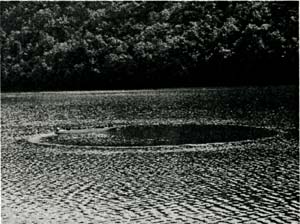
Free running tests were carried out with an 1/72 scaled ship model(L=4.0625m) in the lake. Control of rudder and propeller, and data acquisition were done by the personal computer installed on the model ship. A personal computer on ship model can be controlled and monitored remotely by a wireless LAN. So, it is possible to initiate and terminate each test and monitor measured motions in real time during tests.
Fig.1 View of Turning Test at the Lake
Table 2 shows main sensors used in free running tests to measure the maneuvering motions of the model ship. Rudder angle and propeller rpm were also measured.
Table 2 Measured Data in Free Running Tests
| Sensor |
Measured Item |
| Fiber Optic Gyro |
Heading, Yaw rate |
| Inclinometer(2-axis) |
Heel, trim |
| Pitot Tube |
Speed |
| RTK GPS |
Trajectory, Speed |
|
Model tests have been done for the following types of maneuver both at full load and ballast condition.
- 10°/10°Zig - Zag test
- 20°/20°Zig - Zag test
- 35°Turning test
To see the effects of GM on the maneuvering performance of a container ship, free running tests were done at three different GM conditions(GM=2.6m, 5.0m, 9.4m). The tests with much smaller GM values were desired to see the effects of GM more clearly but they can not be done due to the limit of movable weights.
To reduce uncertainty of test results, more than two times of same tests were done repeatedly for each test. Observed variances were within 4degrees in case of overshoot angles for zig-zag tests and within 0.3L in case of advance and tactical diameter for turning test. During tests, large difference of maneuvering performance between port rudder and starboard rudder were observed. This difference was especially noticeable for 10°/10°zig-zag tests. A large neutral rudder angle(2.3°) was found to be the cause and that was confirmed by simulation study. Large neutral rudder angle is often observed in free running model tests although it is much smaller in full scale ship. So, it is reasonable to take average values of data from both rudders in estimating maneuvering performance. The test results are summarized in Table 3. The values in Table 3 are averaged values of all repeated tests except some outliers.
As expected, there are large difference in maneuvering performance between at full load condition and ballast condition. At ballast condition, the ship has very good course keeping and changing performance while worse turning performance. This is mainly due to a trim at ballast condition same with a conventional container ship. At full load condition, the ship has a good turning performance. In case of course keeping and changing performance, it is not bad but it is also hard to say to be good. Especially, 1st overshoot angle of 10/10, 20/20 Zig-Zag test is not so far from the criteria that it might fail to satisfy IMO standards depending on the design. As GM increases, turning performance becomes a little better but course keeping and changing performance becomes worse. In case of GM=9.4m, the roll motion is so small that the motion is thought to be almost three degree of freedom. Seeing the difference of maneuvering indices between for GM=2.58m and for GM=9.4m, the effects of roll motion should be considered to predict the maneuvering motion on the purpose of meeting IMO standards.
Table 3 Maneuvering Indices of 9000TEU Container Ship Measured from Free Running Tests
| Test |
Index |
Full Load(GM) |
Ballast |
IMO Standards |
| 2.6m |
5.0m |
9.4m |
| 10°/10°Zig-Zag |
1st Overshoot |
17.5° |
16.0° |
14.0° |
3.6° |
16.7° |
| 2nd Overshoot |
16.3° |
15.1° |
15.0° |
1.8° |
35.0° |
| Initial Turning Path |
1.52L |
1.48L |
1.57L |
1.45L |
2.5L |
| -10°/-10°Zig-Zag |
1st Overshoot |
8.0° |
8.9° |
8.2° |
1.7° |
16.7° |
| 2nd Overshoot |
22.9° |
20.8° |
20.9° |
4.2° |
35.0° |
| Initial Turning Path |
1.75L |
1.72L |
1.81L |
2.03L |
2.5L |
20°/20°Zig-Zag
-20°/-20°Zig-Zag |
1st Overshoot
1st Overshoot |
19.31° |
- |
18.8° |
6.7° |
25.0° |
| |
17.8° |
- |
- |
5.6° |
25.0° |
| 35°Strbd. Turn |
Advance |
2.99L |
3.05L |
3.05L |
3.35L |
4.5L |
| Tactical Diameter |
2.71L |
2.75L |
2.84L |
4.64L |
5.0L |
| 35°Port. Turn |
Advance |
3.09L |
- |
- |
3.99L |
4.5L |
| Tactical Diameter |
2.78L |
- |
- |
5.32L |
5.0L |
|
4. CAPTIVE MODEL TESTS AND SIMULATION OF MANEUVERING MOTION
4.1 Mathematical Model
The mathematical model of the ship maneuvering motion is based on MMG model[5,6]. With the body-fixed coordinate system shown in Fig.2, the equations of maneuvering motion with four degrees of freedom are written as follows.
where the terms with subscripts H, P and R represent the hull, propeller, and rudder forces and moments, respectively. QE and QP represent the engine and propeller torques XG and ZG represent the x-coordinate and z-coordinates of the center of gravity of the ship. And the dots on u, v, r, p and n represent the time derivatives of each variable.
Fig.2 Coordinates System and Sign Conventions
Hull Forces and Moment:
Hydrodynamic forces and moment acting on the hull are described as follows:
where X(u) represents the resistance of a ship, ZH represents the vertical center of hydrodynamic forces acting on the hull.
Propeller Forces and Engine Torque:
Hydrodynamic forces and moments due to a propeller can be written as follows:
YP = 0
NP = 0 (3)
KP = 0
where n is propeller rps and Dp represents the diameter of the propeller.
Rudder Forces and Moment:
Hydrodynamic forces and moments due to rudder are expressed as follows:
XR = - (1 - tR)FNsinδ
YR = (1 + aH)FNcosδ
KR = - (1 + aH)zRFNcosδ (4)
NR = (xR+aHxH)FNcosδ
FN = UR2ARfαsinαR
where
αR = δ - δR
δR = δO + γR(v' + l'Rr')(U/uR) (5)
VR = - uRtanδR
η: propeller diameter / rudder height
|