|
3.4 Sensor and Navigation Systems
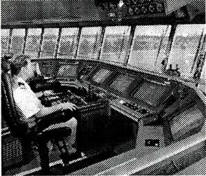
In general, DP vessels are outfitted with sophisticated integrated navigation system solutions on the bridge, see Fig.5. From this central command area the navigators/operators perform multitasking activities in their predominantly monitoring role, which may also include supervision of other vessel's systems, in order to accomplish the operative tasks in navigational safety and operational efficiency.
Sensor system module: A major navigation sensor system on a DP vessel is the Global Navigation Satellite System (GNSS) receivers that provide the accurate position, speed and time. The fully operative GNSS system currently available is the Global Positioning System (GPS) that is operated and controlled by the US DoD. GLONASS is the Russian GNSS and is also available to civilian users, although not fully operative. Galileo is the European satellite system and will have guaranteed global positioning service under civilian control. Galileo will be inter-operable with GPS and GLONASS. It is scheduled to reach full operational capability in 2008 and will then ensure redundancy in satellite-based positioning of DP vessels.
Differential GNSS sensor systems, such as DGPS, are designed for applications demanding reliable, accurate and quality-controlled position and speed as is the case for DP vessels. Two or more receivers observe the same set of satellites, taking similar measurements that produce similar errors when positioned in the vicinity. A reference receiver, placed at a known location, calculates its theoretical position and compares it to the measurements provided by the satellite signals. The difference between the two values reveals the measurement error which is then transmitted as a corrected signal to receivers within the area covered by the DGPS and is able to increase accuracy with a 10-fold.
Fig.5 |
Example of an integrated navigation bridge system solution. |
The second type of position reference system available on most DP vessels is the Hydroacoustic Position Reference (HPR) system. HPR is based on short (SBL), long (LBL) and super short baseline (SSBL) principles or a combination of all. The SBL systems utilises 3 - 4 hull mounted transducers. The position calculation is based on range measurements to three or more transponders. Other relative position reference systems such as Artemis and laser systems may also be used when operating close to other marine structures.
Radar is the sensor system for detecting the environment (landscape, marine traffic, navigation buoys) surrounding the vessel. Traffic surveillance is essential for a DP vessel in operation in order to avoid incoming traffic violating the safety operational zone and thus the risk of collision. The radar sensor's target detection will be supplemented by the independent Automatic Identification System (AIS) that is currently being installed on board the vast majority of ships above 300 GT. AIS is a ship borne system capable of exchanging navigation and ship data between own ship and other ships and coastal stations within VHF range. The system comprises a transponder unit with a VHF transmitter and 2 receivers and a GNSS receiver.
Motion sensors such as Motion Reference Unit (MRU) or Vertical Reference Unit (VRU) are utilising accelerometers and models of gyros to provide the vessel motions. MRU can measure heave, roll, pitch and yaw and is used in many marine application systems such as Helideck Monitoring System (HMS) to analyze helideck motion during helicopter landings to improve safety in hostile weather conditions.
Other navigation related sensor systems are the gyrocompass for heading (direction) measurements, depth sounder for determining water depth and a speed (Doppler) log to measure water and ground speed. Common sensors are also the barometer that sense atmospheric pressure and anemometer to record wind speed and direction.
Navigation system module: Automatic Radar Plotting Aid (ARPA) is a computer-based navigation support system that calculates and displays anti-collision information of multiple targets such as motion vectors, range, peed, course, minimum distance at, and time to closest point of approach. The sensor inputs are ship speed and heading (from speed log and gyrocompass, respectively), relative position and velocity of targets as provided from the radar sensor. ARPA also enables route planning as the operator can insert waypoints and fairways.
Visualization of exact collision risk regions in true motion displays has been proposed [3] as an improvement to the standard ARPA displays. The possibility of operator distraction increases with the amount of target data in multiple encounter situations due to the human limitations in properly processing large amounts of (alpha-numeric) data. The sensor inputs required are the position and true velocity vectors of acquired targets as provided by the radar and/or AIS.
Fig.6 shows an example of the proposed visualization-based collision avoidance support system (VCASS) from the viewpoint of a stationary ship (e.g. a DP vessel in operation) in a heavily congested marine traffic condition. This man/machine interface can conveniently be applied to DP vessels during operation or in transit as it enables efficient traffic surveillance and collision risk assessment from the viewpoint of any selected target [4].
Fig 6 |
Visualization-based Collision Avoidance Support System (VCASS) applied to a DP vessel operating in congested area. Red targets are violating required safety zone. |
Fig.7 System architecture of VCASS module [4].
The Electronic Chart Display and Information System (ECDIS) is a real-time Geographic Information System (GIS) that combines both nautical charts and sensor information into a real-time navigation tool. An ECDIS continuously determines a vessel's position in relation to the topographical conditions, navigational hazards and charted objects. The basic components are; computer processor, digital database, navigation sensor inputs and a colour display. Additional shipboard sensor inputs may include ship's gyrocompass, depth sounder, ARPA radar, AIS.
Integrated navigation displays: Integrating all navigation systems so that they relate to each other and provide the operator with a holistic approach from relevant sensors, is a key to safe navigation and operation. Data that is vital is permanently integrated into the system, recorded and processed on a continuous (real-time) basis. Examples include information from the GNSS, gyrocompass, water depth indicators, and meteorological sensors.
The sensor and navigation systems module of MCSim takes all signals that are to be measured, and utilizes sensor models including noise models (wild points, variance, drifting, bias, etc.) in order to generate realistic feedback signals to the control system. An FMEA module enables various failure conditions to be simulated. The VCASS module (Fig.7) may be connected to MCSim for navigational safety applications.
3.5 DP and Thrust Controllers
DP Controller: The DP controller includes signal processing, observer for state estimation, feedback and feedforward controllers. It thus takes vessel motion, wind and riser angle measurements as input, and generates a desired thrust vector as output.
Thruster control: The thruster control module includes thrust allocation algorithms for distributing the desired thrust on the actuators, and local thrust control algorithms for finding the motor control input from desired thrust.
|