|
3. FRAMEWORK DESIGN CONCEPTS
The design of the OFSMVD framework is based on several goals and philosophies. The goals are in general to provide a reusable set of classes that 1) provide the abstract structure for developing and performing dynamic simulations, and 2) define the most fundamental concepts that are commonly seen across a wide range of possible applications. The philosophy for designing this architecture is to balance the desire to obtain the most comprehensive coverage of the problem domain while maximizing efficiency, flexibility, and portability.
An object oriented application framework is a good approach to this type of problem [8]. This is due to the general nature of frameworks which inherently promote modularity by encapsulating implementation details behind their interfaces. The stability of these framework interfaces enhances the reusability of the generic components provided by the framework. The ability to extend a framework is enhanced by providing explicit hooks to methods which separate interface and behaviors in the problem domain from the context of a particular application. An interesting characteristic of object oriented frameworks is inversion of control. This means that the abstract architecture provided by the framework determines which application specific methods to invoke, rather than the application making the determination (polymorphism in action!). This is the inverse of how traditional libraries work with an application.
Developing an application framework involves the distillation of the problem domain to its most fundamental elements and the interactions between them. Since we are concerned with modeling and simulating physical world processes, the best place to start is with the mathematical problem.
4. MATHEMATICAL BASIS
All of the types of physical systems and dynamic behaviors that are of interest in marine simulation can be expressed by the general nonlinear equation,
where  (t) is a time dependent vector of states and A( (t),・・・) is a vector of nonlinear equations possibly involving the time dependent states and other terms. The steady state version of this equation is,
where  is a constant vector and the state and equation vectors are no longer time dependent. This form is useful for time invariant problems such as dynamic positioning and those involving steady, constant motion.
The numerical solution to Equations (1) and (2) can be performed by a variety of methods. The choice of method depends primarily on which of the two equations is under consideration and secondly on nature of the particular problem under investigation. Issues such as numerical stability and efficiency also come into play when choosing a solution method.
5. OFSMVD ARCHITECTURE
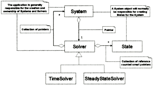
A framework for simulating the behavior of marine vehicles must at the very least deal with rigid body dynamics. The general rigid body dynamics problem, as well as the specialization of floating and submerged bodies' in motion (and at rest), are modeled by Equations (1) and (2). For the OFSMVD framework, three basic classes have been identified and defined to express the general case. These are Solver, State, and System.
5.1 System Dynamics
The Solver class represents the numerical solution method to either Equation (1) or (2). There are two subclasses of Solver, TimeSolver and SteadyStateSolver, which are specializations necessary to address the specific types of problems in Equations (1) and (2), respectively. A Solver object is directly related to one or more State objects that it operates on to advance in time or iterate to a steady value. The State class represents one of the mathematical states in Equations (1) and (2) and is responsible for maintaining its own value and derivative value. It is the responsibility of the System class to create State objects on its own behalf and provide them with their derivatives when requested by a Solver.
A System object can logically be associated with one and only one Solver. When the System creates its States, those States are added to a collection of States maintained by the Solver. A Solver on the other hand, may be associated with one or more Systems. This allows multiple Systems to be "solved" simultaneously, which might be necessary if multiple Systems are somehow coupled.
The relationships between the Solver, State, and System object types are illustrated by the UML class diagram shown in Figure 1.
Fig. 1 Class Diagram for System, State, and Solver Classes.
In Figure 1, all of the associations between Systems, States, and Solvers are shown - the two aggregation associations between Systems and Solvers, the aggregation association between Solvers and States, and the inheritance relationships between Solvers and TimeSolvers and SteadyStateSolvers. The notes attached to the relationships reveal some of the implementation details - the use of pointers and reference counted smart pointers (more on these later). The other notes are used to clarify responsibility issues involving object ownership and creation.
5.2 Marine Environment
While the basic System, Solver, and State classes are sufficient for the simulation of general dynamics, there is much more that can be done to enhance the usefulness for marine simulation. All of the objects that exist and interact in the physical and simulated world do so in the context of an environment. As such, there is an Environment class that represents the virtual world. The elements of the physical environment that are significant for marine modeling purposes can be defined to be the wind and current fields, water waves, and the topology of the above and below water environment. Each of these has their virtual counterparts within the object framework - Wind, Current, Waves, and Topography. These types are considered to be sub-classes of System to allow for the possibility that they might be represented by a mathematical model in the form of Equation (1) or (2). Each of these types can associated with only one Environment, and an Environment may have only one of each. It is important to note that how these types of objects are specifically defined and implemented, how they interact with each other, and how they interact with any other dynamic systems in an Environment, is highly dependent on the nature of the application. For example, consider the differences in environmental modeling requirements for a unrestricted deep water simulation and a multibody simulation in a channel.
5.3 Vessels, Effectors, and SubSystems
All of the other types of System objects that exist within the physical and virtual environments are the bodies that we are concerned with simulating. These are represented by the Vessel class. A Vessel might be a surface ship, submersible vehicle, or even an aircraft, for example. The behavior of a Vessel is governed by a set of equations of motion which are expressed by the parent class (System) as previously discussed. A Vessel responds due the application of forces and moments on the body. The physical objects that apply those forces and moments are Effector objects. These can represent rudders, thrusters, jets, propellers, paddles, etc. A Vessel object may contain many Effector objects but an Effector is associated with only Vessel. It should be noted that the interaction between a Vessel and the components of the Environment that produce forces and moments on the Vessel is specific to the nature of the application. The same can also be said about interactions between Effector objects.
As in the physical world, a Vessel object might also contain systems that exhibit their own dynamic behaviors. Obvious examples are engines and machinery. These are represented by a SubSystem class which is subclass of the System class. A Vessel object may contain many SubSystem objects but each SubSystem is associated with only one Vessel. The normal behavior of the framework is to use the Solver associated with the Vessel as the Solver associated with the contained SubSystem. This can be changed as necessary for a specific application.
5.4 Interactions Between Vessels
Interactions between Vessel objects can occur on many levels and in many ways. These could be categorized into interaction forces and moments that result from operating in proximity to each other and interactions that are the result of direct contact or coupling of the equations of motion. The former of these require special care and are generally specific to the nature of the application being created. However, the case of interaction forces due to proximity can be represented by a VesselInteraction class. The VesselInteraction class is responsible for maintaining the association between two and only two Vessel objects and providing the forces and moments on each. How those forces and moments are computed is again, dependent on the nature of the application. All of the VesselInteraction objects created to support a simulation are contained by the Environment. It is the responsibility of each Vessel object to add the forces and moments from all related VesselInteraction objects to the forces and moments acting on the Vessel from all other sources. Support for performing this function is provided by a method in the Environment class.
In order to support the use of Effector and VesselInteraction objects, the framework defines a ForceMoment class which represents the three orthogonal components of a force and moment vector. It does not have any implicit units or coordinate system (in spite of the component labels referring to x, y, and z axes) associated with it. There is also no implicit or explicit point of application of the force and moment. It is the responsibility of the application developer to define the convention used and to ensure that the convention is followed.
5.5 Value Class
One of the more difficult concepts to model in the framework is the mechanisms by which information is passed to and from framework objects. Specifically, command and control information and generated information such as rudder angle commands and the values of states. The primary consideration is maintaining the integrity of framework objects and their properties. In most cases, those properties are protected from direct access outside of the object.
A single class, Value, is defined to provide both control values to the framework and to retrieve values of interest from the framework. The Value class is logically associated with the System class and all of the System subclass types. However, the Environment is responsible of maintaining the collection of all Value objects. The application can then access all of the Values through the Environment and perform actions on those Values as appropriate.
When a Value is created, it is assigned a role - control or observation, a native data type - real, integer, logical, and an identifying label. The application can query the role, type, and label of a Value to determine appropriate actions to be performed.
5.6 Exception Handling
The OfsmvdException class is used to provide a consistent and defined interface that supports the exception handling mechanism of the C++ language. In C++, an exception is a potentially unrecoverable error resulting from an attempt to perform an undefined operation, such as divide by zero. The language defines several types of exceptions, all of which will propagate up to the application through the framework if they occur. The framework might also internally determine that an exceptional condition exists. For example, instructing a SteadyStateSolver to perform a time step. In any case, when the framework generates an OfsmvdException, it will indicate what went wrong.
5.7 Associations Using Pointer Types
Most of the associations between framework objects are aggregation relationships. As previously mentioned, an aggregation implies that the lifetime of an aggregated object is not managed. To support this behavior within the framework, pointers and dynamic memory allocation is used. Objects and data types are instantiated (created) either statically or dynamically. Static allocation is performed by explicitly declaring a variable of some type, and the compiler internally handles all the memory management. Dynamic allocation is performed by explicitly allocating memory for the object or data, at run time. Prior to termination of the application, allocated memory must be released. If it is not released, a memory leak will occur.
The space that is dynamic allocated for an object or data type is accessed via a pointer to the location in memory. The framework defines three types of pointer classes that encapsulate raw memory pointers. These are Pointer, OwnedPointer, and RefPointer. The Pointer class is used to represent a raw pointer and makes no assumption about what the pointed to memory represents or who is responsible for releasing allocated memory if necessary. The OwnedPointer class is used to encapsulate a Pointer. However, the OwnedPointer class assumes that it "owns" the memory and that it is responsible for releasing that memory when the OwnedPointer object is destroyed. The OwnedPointer concept corresponds to similarly defined pointer types which are refered to as smart pointers" or "automatic pointers"
Pointers are extremely efficient for exchanging data since a copy of the data does not need to be made in order for the exchange to occur. Exchanging pointers will instead, copy the address of the pointed to memory. However, the responsibility of ownership is clouded when multiple copies are involved.
The mechanism that is employed by the framework to ensure that ownership responsibility is maintained properly is reference counting. This mechanism is encapsulated by the RefPointer class. Like the OwnedPointer class, RefPointer assumes ownership responsibility for dynamically allocated memory. However, when a RefPointer is copied, the count of references to the object is increased by one, and a pointer to an internal data structure containing the owned pointer and the count is copied. When one of the RefPointer objects is destroyed, the reference count is decreased. When the reference count becomes zero, the allocated memory is released automatically. The use of reference counting allows the framework to benefit from the efficiency of raw pointers and while providing automatic memory management.
All three pointer classes are defined using templates. A template allows the classes to be written without direct knowledge of the data type pointed to. In order for a template class to be created, the data type must be explicitly declared at creation. All of the classes defined by the framework which have associations implemented using either Pointer, OwnedPointer, or RefPointer, have type definitions for those pointer types. For example, the Vessel class has associations that require the use of Pointer and RefPointer. Type definitions for a Pointer to a Vessel (VesselPtr) and RefPointer to a Vessel (VesselRefPtr) are provided. Type definitions for collections of pointer types to framework classes are also provided (VesselRefPtrCollection for example). It is useful to note that cyclic relationships between reference counted pointers can lead to problems. This type of situation is specifically avoided in the framework implementation.
5.8 Degrees of Freedom
The framework provides a degrees of freedom class, DOE, purely to document the nature of a Vessel model. Two separate instances of DOF are contained by a Vessel, one for the degrees of freedom that the Vessel models and the other for the degrees of freedom that are solved. The difference is that the degrees of freedom modeled are those that appear to an outside observer while the degrees of freedom solved are those that have internal mathematical models. For example, consider a Vessel model that has six degrees of freedom composed of seakeeping motions generated from frequency domain transfer functions and three degrees of freedom (horizontal plane) maneuvering motions from solving the surge, sway, and yaw calm water equations of motion. In this case, there are six degrees of freedom modeled and three degrees of freedom solved.
5.9 Complete Software Model
The complete model for the framework is shown in Figure 2. All of the associations and relationships that have been discussed are represented in the class diagram.
Fig.2 Class Diagram of the OFSMVD Framework.
6. ADDED BONUS CLASSES
To help minimize the work required to utilize the framework, several implementations of Solvers are provided. For TimeSolvers, the numerical methods implemented include Euler, Adams-Bashforth, Mid-Point, 3rd and 4th order Runge-Kutta, and 5th order adaptive Runge-Kutta [10]. For SteadyStateSolvers, a Steffensen method [10] solver is provided. All these Solver implementations can be used as is, without any additional sub-classing.
Also included are three Vessel class implementations that have predefined equations of motion for a 3 (sway, surge, yaw), 4 (sway, surge, yaw, roll), and 6 degree of freedom body. . The equations of motion utilized are written assuming a body fixed coordinate system with the origin at the center of gravity. No Effector objects are included in these Vessel sub-classes.
|