|
1) Equal Screen Size Pattern
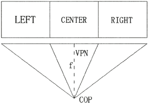
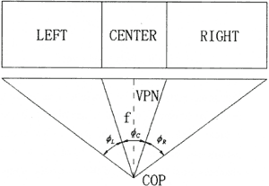
For the example of three-channel flat screen system, three channels are named LEFT, CENTER, RIGHT respectively, see Fig.4.
Fig. 4 Equal Screen Size Pattern
In Equal Screen Size Pattern, the height, width of screen of each channel are equal, we have:
WL=WC=WR=W
HL=HC=HR=H
In marine simulator, the eye-point of visual system is usually set to somewhere just above steering wheel. Depending on the condition of installing place, we can select suitable distance from eye-point to screen f, width of screen w and height of screen h to get correct geometry relation of the scene. Because w and h in most commercial graphics system always keep in the aspect of 4:3, therefore, it's enough to select only f and w to get suitable angle of field of view and correct geometry between object and object in the generated scene. When setting parameters of viewing frustum, we can see from Fig.4, the eye-point of these three channels have the same position of COP(Center Of Projection), and z axes of viewing coordinates of each channel are same, it's VPN(Viewing Plane Normal).
For example, if we call the function of glFrustum(left,right,bottom,top,near,far) in OpenGL to define the viewing volume for each channel, we have:
a) For Center channel:
left = -W/2
right = W/2
bottom = -H/2
top =H/2
near = f
b) For Left channel
left = -3*W/2
right = -W/2
bottom = -H/2
top = H/2
near= f
c) For Right channel
left = W/2
right = 3*W/2
bottom = -H/2
top = H/2
near = f
Obviously, discussing the viewing volume, only the center channel is a symmetric truncated pyramid, both left and right channel are sheared. It is interesting that ' only to modify the parameter "left" and " right" of left and right channel a little bit, we can simulate the obstacle effect of frame of the bridge window and the frame of display devices. For example, assuming that the width of frame is d, changing the parameter of right channel left to W/2+d and right to 3*W/2+d, we can simulate a window frame between left window and center window.
2) Equal Angle of Field of View Pattern
As Fig. 5 shown, in equal angle of field of view pattern, every channel within this visual system has the same angle of field of view,
φL = φC = φR = φ
Fig.5 Equal angle of field of view pattern
Obviously, using equal angle of field of view pattern to implement multi-channel mergence, the screen size of center channel, the screen size of left and right channel are totally different. Furthermore, the screen size of each channel is difficult to keep in the aspect of the screen of 4:3. But for equal angle of field of view pattern, each graphics channel has the same angle of field of view, it's relatively easy to keep the equal burden for each graphics channel. Especially; for the graphics system using hardware channel synchronization techniques, the system can get higher update rate. Similarly, for equal screen size pattern, because the screen size of each channel is equal, the outline of the screen is pretty, and it's easy to keep in the aspect of the screen of 4:3. But the angles of field of view in each graphics channel are extremely different, sometimes, the angle of field of view of center channel is two times than left channel and right channel. For graphics system in which hardware synchronization of multi-channel is employed, we have to set the update rate of center channel as the update rate of whole visual system. Obviously, we get lower graphics update rate now.
2.2 Polygonal Screen System
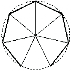
Polygonal screen as shown in Fig.6, is substantially the flat screen system.
Fig. 6 Polygonal screen
Polygonal screen can be configured using several (odd) flat screens combined as inscribed polygon of a circle. Each channel has the same viewing volume parameters, but the VPN vectors of two adjoining channels exist difference of the horizontal angle of field of view of one channel. Because every channel projecting it's own image to it's own flat screen part within the polygon screen, therefore polygon screen system has the same advantages of flat screen. The horizontal angle of field of view can be bigger than 120 degrees even to 360 degrees. It's not necessary that the projector used in polygon screen visual system has the ability of geometry correction. Unfortunately, a horizontal line projected on polygon screen will become a broken line viewing from the eye-point. When a moving object move across the border of two adjoining channels, a wrong impression would be occurred that the moving object seems to change its course suddenly.
Polygonal screen multi-channel visual system is suitable to be used in auxiliary own-ship or in primary own-ship of lower cost.
2.3 Cylindrical Screen System
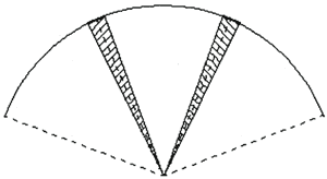
Cylindrical screen usually is installed around the simulated bridge like a theater, it's shown in Fig. l-b. The simulated scene projected on to the large scale cylindrical screen will give operator strong impression of immersion. Now almost every bridge simulator with high performance is configured of cylindrical screen multi-channel visual system the horizontal angle of field of view can be up to 360 degrees. Similarly as polygonal screen system each channel has the same viewing volume parameters, but the VPN vectors of two adjoining channels exist difference of the horizontal angle of field of view of one channel. Because perspective projection is implemented in the scene generation using CGI(Computer Generated Image ) technology, image is projected on a flat plane, projection plane. If this image is projected to the cylindrical screen, geometry distortion will occur, it's shown in Fig.7.
Fig.7 Image distortion due to using cylindrical screen
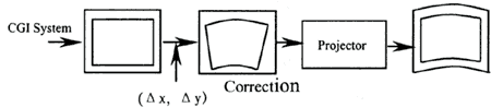
Thereby, before the image generated by CGI is projected onto the screen, the image has to be corrected as shown in Fig.8.
Fig.8 Geometry correction
With correct correction, objects within the scene keep in accurate relation when view from the eye-point of the system, e .g. horizontal lines are still horizontal lines and vertical lines are still vertical lines. Several method of seamless connection of image between ad joining channels can be implemented when using cylindrical screen visual system, the most effective method is edge blending. Actually, image after geometry correction, one pixel error in vertical direction between two adjoining channels can not be exactly avoided, one pixel gap or one pixel overlay existing between two adjoining channels is quite often, this will cause a black line(caused by gap ) or a white line( caused by overlay ) at the edge. It's very difficult to be seamless. When edge blending is adopted, it's necessary to change the parameter of viewing volume of each channel a little bit, e.g. to extend width of projection plane through parameter left and right of each channel, width extension converted to the angle of field of view is about one to three degrees. Obviously, an overlay about 25 to 75 pixels between adjoining channels emerges(shown in Fig.9). Adjusting ALPHA data of each pixel of two adjoining channels within this overlay carefully, we can get really seamless wide angle of field of view scene. Unfortunately, as described above, projector used in cylindrical screen visual system must have the ability of geometry correction or to add geometry correction equipment between graphics output and projector input. Nowadays, the price of projector with geometry correction and edge blending ability is normally three to four times as the projector without the ability of geometry correction and edge blending. This is a very large investment for marine simulator especially in the visual system employed much more numbers of projectors.
Fig.9 Overlay area between adjoining channels
|