|
資料―1
INTERNATIONAL MARITIME ORGANIZATION
IMO
E
MARINE ENVIRONMENT PROTECTION
COMMITTEE
49th session
Agenda item 4
MEPC 49/INF.10
11 April 2003
ENGLISH ONLY
PREVENTION OF AIR POLLUTION FROM SHIPS
On-board NOx measurement and monitoring
Submitted by Japan
SUMMARY
Executive summary: This document provides information on Japan's on-board study
on NOx measurement and monitoring of three sample ships
Action to be taken: Paragraph 5
Related documents: DE 46/INF.5
Introduction
1 It is described in the NOx Technical Code that the deviation of the NOx value from the shop test results at the time of sea trial is 10% and when residual fuel is used the allowance will be 10%, but not more than 15%, in total. However, these figures were not based on the actual monitoring data.
2 Until recently, we had no experiences on continuous NOx monitoring under the condition of commercial voyages that use various kinds of residual fuels so far. Therefore, Japan started a three-year on board study of NOx measurement from FY2001 aimed at the following 3 goals:
.1 Developing feasible and practical NOx direct measurement and monitoring methods which are accurate and are not be burdensome, so as to unduly delay the ship or to require an in-depth knowledge among crew;
.2 Investigating NOx conversion rates of the nitrogen content included in fuel oil; and
.3 Investigating NOx emission deviation rates from the shop trial data.
Sample ships
3 Sample ships were selected to cover every type of engine (MAN-B&W, Wartsila and Mitsubishi) in the market now. And also selected were different type of vessels (VLCC, container and another) and also the routes of vessels were different. One-year measurements for IKOMASAN and NYK ANTARES have been completed and a measurement for ship B is now being carried out. Fuel oil samples were taken from the engine inlet and analyzed by DNVPS. These were then tested by the constant volume combustion chamber testing rig.
Table: Principles of Sample Ships
| |
Ship-owner |
Name of vessel |
Type of vessel |
Type of main engine |
Output x Engine speed |
| 1 |
MOL |
IKOMASAN |
VLCC |
Mitsui-MAN-B&W
8S80MC |
34,100 PS x 68 rpm |
| 2 |
NYK |
NYK ANTARES |
Container |
DU-Sulzer 11RTA96C |
72,467 PS x 94 rpm |
| 3 |
A |
B |
(another) |
Kobe-Mitsubishi
8UEC60LSII |
18,953 PS x 99 rpm |
|
Results of the study
4 The summary of the results of the study was reported to the 46th session of the DE Sub-Committee (DE46/INF.5) and the full version of a progress report is attached as the Annex to this document. Conclusions of the report are as follows:
.1 It was verified that the zirconia analyzer was applicable for NOx monitoring with respect to reliability, accuracy, durability and frequency of calibration;
.2 Deviation level on the NOx emission rate will exceed 15% relative to shop trial data in some cases. This is caused by the quality of the fuel oil; and
.3 The NOx conversion rate of the nitrogen content in the fuel oil is found to be 55%, while further verification will be needed. This means that further study on allowance of 10% for the use of residual fuel oil and on allowance of 15% for both the simplification of measurements on board and the use of residual fuel oil would be necessary.
Action requested of the Committee
5 The Committee is invited to take note of this information.
***
ANNEX
Progress report on on-board NOx measurement and monitoring
1 Preface
Regarding the prevention of air pollution from the ship, IMO has adopted the Annex VI of MARPOL 73/78 in 1997. Japan has carried out a continuous NOx monitoring on board test by using 3 ships under the commercial operation condition from FY2001 prior to the start of the regulation to find out practical and useful devices of monitoring. This reports the details of the test to give a future reference of the NOx on board monitoring.
2 Target of the study
As shown in below, at the time of the periodical survey of the IAPP certificate, the NOx monitoring device is prescribed as one of the three measures of the verification procedure of IAPP certificate.
.1 Parameter check method
.2 Simplified measuring method
.3 Continuous NOx monitoring method
However, so far, we have no experiences of long term continuous NOx monitoring of the propulsion engine, under the condition of commercial voyages that uses various kinds of residual fuels. In NOx technical code, it is described that the deviation of the NOx value from the shop test results at the time of sea trial is 10% and when residual fuel is used allowance will be 10% but not more than 15% in total. But this seems that these figures were not decided based on the concrete data.
Therefore, Japan carried out the test in order to clarify the following 3 items.
.1 Development of low cost, maintenance free and more practical continuous NOx monitoring devices.
.2 Clarification of the NOx conversion rate of the nitrogen that is included in the fuel oil.
.3 To get more information about the NOx generation characteristics when using residual fuel oil.
(Specially the range of deviation from the time of shop test with Diesel oil.)
3 Outline of the project
The project was carried out as 3 years project from the fiscal year of 2001. We have selected three vessels that have different types of ship type, route of voyage and engine type. It is planned to carry out the continuous NOx monitoring for almost 1 year each. Also, all the fuel oil, which were bunkered in this period, are sampled for component analysis especially for nitrogen content and carried out the combustion test by using constant volume test rig.
| The 1st vessel |
M/V 'IKOMASAN' |
VLCC |
Mitsui-B & W 8S80MC |
| The 2nd vessel |
M/V 'NYK
ANTARES' |
Container |
DU-Sulzer 11RTA96C |
| The 3rd vessel |
M/V 'B' |
(another) |
Kobe-Mitsubishi 8UEC60LS II |
|
4 Selection of the sample ships
Test vessels were selected to cover every type of engines (MAN-B&W, Wartsila and Mitsubishi) in the market now. And also selected different type of vessels (VLCC, container and PCC) and also route of vessels were different. The test was started from the fiscal year of 2001 using the first and second vessels. From the fiscal year 2002, the third vessel was joined to the project
5 Selection of sensors
5.1 Characteristic of Zirconia (ZrO2) Sensor
Zirconia (ZrO2) sensors are widely used in after-treatment system of exhaust gas using three-way catalyst especially for gasoline engine for automobile, with its quake- and shock-proof ability, and maintenancebility. It is also popular for measurement purposes, for vehicle application, as well as for marine application such as for inert gas leak detector in tanker. Table 5.1.1 shows ZrO2 sensors in various measurement uses.
Table 5.1.1 ZrO2 sensors in various measurement uses (as of year 2000)
Delivery record of Automotive exhaust gas A/F analyzer using O2 sensor
More than 4,500 units |
Delivery record of Tanker IGS(Inert gas system) O2 analyzer
More than 850 units |
Delivery record of Tanker IGG(Inert gas generator) O2 analyzer
More than 150 units |
Delivery record of Automotive exhaust gas ZrO2 NOx analyzer
More than 150 units |
|
5.1.1 Comparison of Sensors for NOx Measurement
Sensors with principles such as ZrO2 method, chemi-luminescence detection (CLD), non-dispersive infrared detection (NDIR), ultraviolet ray detection, and controlled potential electrolysis can measure NOx. The sensors are operated under normal temperature, except for the ZrO2 sensor which is operated under high temperature, and require sampling systems with suction pump or water ejector. Considering the on-board usage, the sensor that has tolerance for vibration and shock at installed position and has maintenancebility is desirable. Table 5.1.1 shows comparison among measurement principles. NDIR and ultraviolet ray sensors which are easily effected by vibration and shock are excluded here.
Table 5.1.1 Comparison among Measurement Principles for NOx Measurement
As is shown in the table, ZrO2 sensor has tolerance for vibration and shock at installed position, simple configuration for maintenancebility, and equivalent function and performance to CLD. Thus, one can assume that it is the most suit principle for on-board usage, which has various limitation for gas measurement.
ZrO2 sensor is very useful due to the fact that it is capable of measuring NOx and O2 simultaneously only with a single sensor, which eliminates installing NOx analyzer and O2 analyzer separately on-board.
5.1.2 Analyzer Using ZrO2 Sensor and its Principle
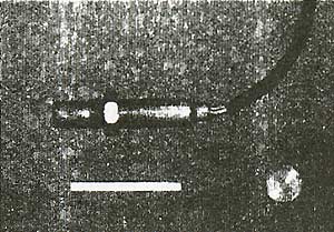
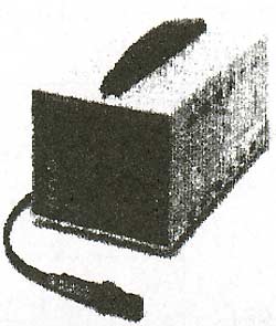
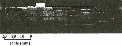
Figure 5.1.2.1 shows a ZrO2-type NOx analyzer which is on the market at the moment. In-situ NOx sensor (figure on the upper left) can be attached directly to measuring position so that it requires no gas sampling. The signal is processed and displayed on the receiver (figure on the upper right). Practically, in-situ measurement is possible for automobile where exhaust pipe is comparatively small. Sampling with ejector will be more suitable for ships with large exhaust pipe in order to measure exhaust gas at the center of the pipe.
|
Figure 5.1.2.1
|
A Model of ZrO2-type NOx Analyzer
|
Next, measurement principles are explained. Gas is measured at the element, 20 mm long and a few mm thick, shown in fig. 5.1.2.1 (lower). Figure 5.1.2.2 is enlarged diagram of the element.
Figure 5.1.2.2 Principle of ZrO2 Sensor Element
|