|
Application of Pressure Distribution Method
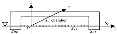
The pressure distribution method (P.D.M) is applied to the analysis of the hydrodynamic forces in this study. In this method, the zero draft is assumed. The variation of the water level in the aircushion is directly considered when the pressures are solved. This is a present approximation method. The coordinate system is illustrated in Figure 2. The boundary plane of the free surface in the aircushion is expressed as SAF.
Figure 2. Coordinate system
In the pressure distribution method, the velocity potential φ and the pressure P are defined as:
Φ(x,y,z;t)=iωaφ・e-iωt
P(x,y,z;t)=-ρgap・e-iωt
where ω is angular frequency, a is wave amplitude, ρis the fluid density
and g is the acceleration of gravity. "i" stands for the complex value (-1)1/2.
In addition, the velocity potentialφis given as follows with Green's function G:
| (Enlarge: 3KB) |
 |
where SH that is a region of the integration means a boundary of a body bottom.
Then, the boundary condition of the general free surface is expressed as follows:
In addition, the boundary condition on the body surface, which is a bottom
of a floating body on z=0 is given as
where p is the pressure on the body bottom. K stands for the wave number in case of deep-water condition, and is ω2/g.
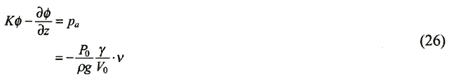
In case of the free surface in the aircushion, the condition of the kinetic equilibrium can be expressed as following linearized Bernoulli's equation:
where Pa represents the pressure in the aircushion
and  represents the variation of the free surface. The
boundary condition such as following equation is derived by considering equation (24) and the kinematical
condition:
Now, since the pressure in the aircushion is obtained by equation (5), equation (25) can be rewritten as:
where ν is expressed as
| (Enlarge: 2KB) |
 |
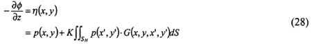
By the way, in the pressure distribution method, the boundary integral equation is generally given such as following expression:
where SH means the bottom surface of a floating body and η is defined as:
| (Enlarge: 2KB) |
 |
Now, if follows is defined
Equation (28) can be expressed as:
| (Enlarge: 3KB) |
 |
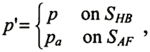
where, SH includes SHB and
SAF.
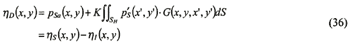
So, if an observation point (x,y) is put on SHB, equation (30) becomes
| (Enlarge: 3KB) |
 |
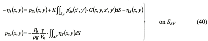
In case that there is the point on SAF, the integral equation can be expressed as follows:
| (Enlarge: 3KB) |
 |
One should note that Pa in equation (32) is given by equation (26) too.
Next, the boundary values that are a left term of equation (32) are discussed.
The boundary value η(x,y) is just the vertical displacement around z=0. Therefore, its variable
has been a known value in general boundary integral equation methods. However, η(x,y) in the aircushion
is unknown because we do not have an information of a distraction behavior of the free surface before
the problem is solved.
Diffraction problem
In the diffraction problem, the boundary value is usually obtained on the body bottom SHB such as:
where ηss is the scattering wave, ηI is the incoming wave and ηD is the diffraction wave. Therefore, the following boundary value is given:
ηD=-ηI (34)
In the case of the present problem, the diffraction wave is given by the following expression:
ηD=ηS+ηI (35)
The boundary value of equation (32) is given by equation (35). Therefore, the boundary integral equation on SAF for the diffraction problem can be expressed as:
| (Enlarge: 5KB) |
 |
accordingly,
| (Enlarge: 3KB) |
 |
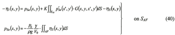
In the above integral equation, a point to which special attention should be paid are that the unknown variable is not only the pressure but also the scattering wave ηS. Then, a following equation is used for another equation,
| (Enlarge: 2KB) |
 |
where, because ν(x,y) stands for the volume change of the aircushion, it is obtained by just the variation of the water plane in the aircushion. Therefore, ν(x,y) is given by
where the integration of equation (39) is carried out in just one aircushion.
From the above formulations, simultaneous equations for the diffraction problem are derived in the following expressions:
| (Enlarge: 6KB) |
 |
The integral equation for the pressure on the body bottom can be expressed such as a formula of equation (31).
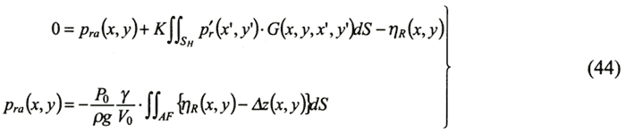
Radiation problem
The boundary condition for the radiation problem is usually obtained by just the mode shape functions. Then, the integral equation is obtained as follows:
| (Enlarge: 3KB) |
 |
where ηR generally represents a mode shape function. However, here, it is the variation of the water plane due to the radiation wave in the aircushion. The radiation wave in the aircushion is unknown in like manner as the diffraction problem. Therefore, ηR is an unknown variable. Equation (27) can be rewritten to
| (Enlarge: 3KB) |
 |
The expression for the pressure pa, is same as equation (38). Then, the volume change of the aircushion is given by the radiation wave and the deflection of the ceiling of the aircushion. Thus the volume change is expressed as follows:
where Δzr is the vertical displacement of the ceiling, and usually corresponds to the mode shape function ηr(x,y) at same place. Because the pressure pa and the wave elevation ηR are unknown values, the equation becomes the simultaneous equations in the same manner as equation (40). The simultaneous equations are derived as follows:
| (Enlarge: 6KB) |
 |
The following integral equation corresponds to the equation for the pressure p on the body bottom
| (Enlarge: 3KB) |
 |
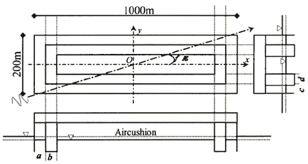
CALCULATION MODELS
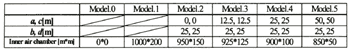
The idealization of the air supported flexible structure is illustrated in Figure , however, the draft of the structure is zero in the numerical calculations. Calculation models and wave conditions correspond in real scale. The dimension of calculation models has 1,000 m in length and 200 m in breadth. Mass of the models corresponds to the draft of 2 meters. A bending stiffness per width corresponds to 1.0E + 10 Nm2/m. Angles of the incident wave 0, 30, 60 and 90 degrees. Water depth is 500 m that corresponds to almost deep-water conditions against the calculated waves.
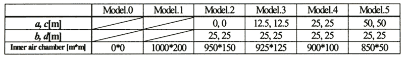
Table 1 shows the principal particular of the aircushion areas of numerical calculation models. Model-0 has no aircushions (i.e., it is a normal pontoon flexible body). Model-1 is supported by just the aircushion (the whole bottom area is an aircushion). Model-2 to Model-5 have two aircushions divided by a buoyant body having width of b and d. In the real numerical calculations, the draft is zero at whole bottom surface.
Figure 3. Idealization of air supported flexible body for numerical calculation
Table 1. Principal particular of aircushion areas of calculation models
| (Enlarge: 14KB) |
 |
|