|
RESULTS OF CALCULATION
First, result of this simulation and result using actual ship are compared. Regarding the heading angle (Fig. 5) and the change in ship advanced speed (Fig. 6), the result of numerical simulation and actual ship sea trial data are very close. However, there is a difference in the turning trajectories in Figure 4. We could have improved matching of data of the two results in the turning trajectories if we have modified the hydrodynamic models and the hydrodynamic force derivatives. However, as we thought that the above discrepancy would create no problem when we apply the result of the simulation to find the tendency of the "whirling motion". Therefore we have performed our analysis without changing anything.
Table 1. Principal dimensions
| Ship |
Towing Ship |
Towed Ship |
| Kind of Ship |
Bulk |
Cargo Ship |
| Loading Condition |
Ballast |
Ballast |
| Hull Data |
| L(m) |
230 |
160 |
| B(m) |
32.2 |
23.5 |
| d(m) |
7.24 |
5.2 |
| τ(m) |
1.05 |
3.78 |
| Cb |
0.82 |
0.6 |
| Cm |
0.95 |
0.88 |
| Cpa |
0.75 |
0.8 |
| Cwa |
0.9 |
0.9 |
| ∇(m3) |
4.40E+04 |
1.17E+04 |
| lcb (%) |
-2.17 |
-3.13 |
| m(kg) |
4.51E+07 |
1.20E+07 |
| mx(kg) |
1.44E+06 |
2.28E+05 |
| my(kg) |
2.40E+07 |
7.84E+06 |
| Izz(N-m) |
8.47E+10 |
9.88E+09 |
| izz(N-m) |
9.07E+10 |
1.42E+10 |
| Rudder |
| AR(m2) |
34.8 |
22.1 |
| hr(m) |
6.9 |
3 |
| λ |
1.38 |
1.57 |
| Propeller |
AU4-55 |
|
| D(m) |
9.7 |
5.7 |
| P/D |
0.71 |
1.14 |
| n(rps) |
1.95 |
0 |
| tp |
0.2 |
0 |
| Z |
4 |
4 |
| Rope coefficient |
| fore(N/m) |
1.00E+05 |
1.50E+05 |
| aft(N/m) |
1.00E+05 |
1.50E+05 |
| Start condition |
|
|
| Us(m/s) |
6.5 |
5.5 |
| rs(rad/s) |
0 |
0 |
| β(rad) |
0 |
0 |
|
Figure 3. A sample of trajectory simulation (KTS:δ= 10 deg)
Figure 4. Comparison of the turning trajectories (δ= 35 deg;■:Exp,◆:Cal.)
Figure 5. Comparison of the velocity of the heading angle (δ= 35 deg;■:Exp,◆:Cal)
Figure 6. Comparison of advanced speed ( (δ= 35 deg;■:Exp,◆:Cal)
Figure 7. Calculated trajectories of Normal Towing System
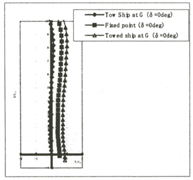
Figure 7 shows trajectories of centers of gravity of both ships when both ships are going straight ahead using the normal towing method. Figure 8 shows positions centers of gravity and trajectories of mooring points of both towing and towed ships. Coordinates are non-dimentionalized by the length of the towing ship. Figures 9 and 10 indicate time histories of relative heading angle between bows of the towing ship and the towed ship. It is apparent that the "whirling motion" is generated when the ordinary towing method is used and amplitude of the "whirling motion" decreases when the Kite Towing System is used.
It shows that towing forces and moments are not balanced at the initial stage, but the ships will go straightforward without using any rudder force. They will turn after some time passed. Turning of both ships occurs because the balanced position between two ships changes so that the amount of hydrodynamic forces is changed and both ships are pulled each other by the towing rope tension.
If towing is started from the steady-state position where towing force is balanced, the steady going-straight-ahead performance can be explicitly improved. However, it is difficult to estimate the steady-state equilibrium position beforehand in the situation of actual towing, therefore in the practical operations, the maneuver with the use of rudder force to some extent is expected. Figures 11 and 12 show the time history of tension that acts on the towing rope. When KTS is used, the dynamic tension such as snap tension does not occur. Once the steady state towing is maintained, the KTS towing tension reduced soon.
Changing the rudder angle from -35 degrees to +35 degrees in steps of 5 degrees performs the turning test of KTS. When the rudder angle is a positive, the ships turn to the right that is the "inside towing method" (turn-around radius of the towed ship is inside the turn-around radius of the towing ship). In the contrary, when the rudder angle is the negative, the ships turn around by the "outside towing method". The turn-around loci at the rudder angle +15 degrees and -15 degrees are shown in Figure 13. Relative heading angle between the towing ship and the towed ship is shown in Figure 14. When turning in the right and left with the same rudder angle are compared, it is seen in the figures that the turning radius in the case of left turn (outside towing method) becomes larger. This phenomenon is important in the actual operation. Even in the single turning operation, the hydrodynamic forces acting on the towing hull changes due to the change of the turning radius changes.
 Figure 8. Calculated trajectories of KTS (δ= 0 deg)
Figure 9. Time history of the relative heading angle (Normal Towing System
δ= O deg)
Figure 10. Time history of the relative heading angle (KTS:δ= O deg)
Figure 11. Calculated towing tension of Normal Towing System
Figure 12. Calculated towing tension of KTS
Figure 13. Calculated trajectories of KTS (δ= ±15 deg)
Figure 14. Time history of the relative heading angle (KTS: (δ=±15 deg)
|