|
ESTIMATION OF WAVE FIELD AROUND THE SHIP
As mentioned in the introduction, some sophisticated methods for estimating wave directional spectrum from ship motions and RAOs of them were proposed. The relative wave motion measured by video image processing, mentioned above, can be used as information for these analyses. However RAOs, for example estimated by strip theory, originally include some error in amplitude and phase, and tend to change by loading conditions, consumption of fuel and operation of anti-rolling devices. Moreover, the ship motion caused by forces other than waves, for example wind and maneuvering, leads to serious error of these analyses.
Conversion from Relative Wave to Absolute Wave
In the analysis proposed in this paper, for avoiding the instability caused by above-mentioned factors, the relative wave motions measured at some positions along the ship's side are converted to absolute waves by subtracting the vertical motions of the cameras. The vertical motions are calculated by double integral of vertical accelerations, or by summation of vertical displacement due to heave, pitch and roll. The influence of inclination on the measured value by vertical accelerometers can be corrected by taking into account the inclination angles of roll and pitch. In displacement calculated from vertical acceleration, drifting or long period deviation from the original mean value can be appeared as the results of accumulation of numerical errors. Such deviation is eliminated by a numerical filter.
By this operation, if the effect of radiation and diffraction waves is small, the amplitudes of RAOs of the converted absolute waves are simplified to unity and the records are treated as the ones from a running wage gauge array. The effect of radiation and diffraction waves are tested by comparing the converted absolute wave on the model ship with those obtained by an array of wave gauges without the model running in the same wave conditions. The results will be presented in the following chapter, in Figure 9.
Estimation of Wave Field from Absolute Waves
It is well known that the wave directional spectrum can be estimated by a wage gauge array, using MLM, MEM, BEM and so on. However the converted record includes some effect of radiation and diffraction waves and when the array is running in following or quartering seas the original wave frequency becomes a three-valued function of the encounter frequency. These factors sometimes lead to an instable estimation. Here a more simple analysis is tried.
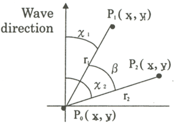
The simple analysis just estimates the three quantities of wave, i.e. height, period and direction, based on the geometric relation between a regular wave and wave gauges. From Figure 8 the following equations can easily be derived.
Figure 8 Coordinate system
where ε01 and ε02 are the
phase difference between the records by the wave gauges of P1 and P0
, P2 and P0 respectively. λ and T are
the length and period of incident regular wave.
For irregular waves the phase difference is defined as the following relations, i.e
εij=tan-1 {Quij(ω)/Coij(ω)} (4)
where Coij(ω) and Quij(ω) are the co-spectrum and quadrature spectrum of the cross spectrum of wave records Sij(ω) at i and j points, respectively.
As to the wave frequency, the peak frequency of the encounter wave spectrum, ωp is selected. The mean wave period, T01, is assumed as 0.73Tp as the relation at the Pieson-Moskowitz type wave spectrum, where Tp is the wave period corresponding to the peak frequency. The significant wave height is the average value of three points.
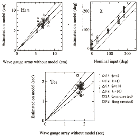
In order to investigate the performance of the simple analysis (SA) a model test was carried out in a basin, which has a multi-directional wave generator. The relative wave motions along the side of the model ship were measured by capacitance type sensors because the experiment was just for investigating the performance of the analysis methods. Some estimated results of significant wave height (H1/3), wave direction (χ) and mean wave period (defined by the spectrum area and the first moment of spectrum; T01=0.73Tp) are shown in Figure 9.
Accuracy
Figure 9. Estimation of wave parameters by simple analysis (SA) and parametric
method (PM) (n: the exponent of directional spreading with the form of cosnθ)
In this figure the results estimated by the parametric method ( Yoshimoto
et al., 1994, see Appendix)(PM), one of the directional spectrum analysis methods, are also included
for comparison. In this analysis the input data is the same as the simple analysis, i.e. the converted
absolute waves at three locations. The broken lines in the figure show the errors of ± 15% for H 1/3,
±30 degrees for χ and ±20% for T 01 respectively. From the figure it is confirmed
that most of the estimated results are between the broken lines and that the accuracy of the simple analysis
is close to the parametric method as long as the main three parameters of waves are concerned. |