|
ANNEX
Abstract of the Investigation on performance of Circular Polarization SART from Research and Study on Performance Improvement about SART
This study was conducted by Japan Ship-Machinery Quality Control Association in cooperation with Japan Coast Guard and other related organizations.
Visibility of SART signal on radar PPI is greatly affected by, among others, the condition of sea surface. Capability of response of SART to radar is affected by change of directivity of antenna which is floating on sea wave and by interruption of radio transmission caused by the sea wave. The polarization of SART has been defined as horizontal in the performance standard of IMO A.802 (19), because the polarization of 9GHz radar is also defined as horizontal. However, SART antenna will be in rolling and pitching motion at sea, and then the polarization plane will nor be always horizontal. This results in the loss of received power at radar antenna and then in reduction of detectable distance and probability of detection of the SART signal. The loss of received power due to the change of polarization plane would be avoided by using circular polarization But, a fundamental loss (by 3 dB) shall happen when radar antenna of horizontal polarization receives SART signals of circular polarization. This loss may affect the visibility of SART signal of circular polarization on radar screen.
Therefore, a series of trials were conducted in order to investigate the performance of a SART which antenna polarization was circular.

Figure-1
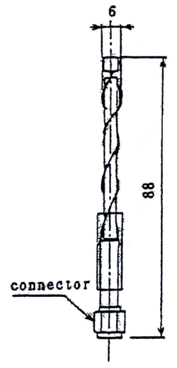
The structure of
the helical circular polarization antenna |

Figure-2
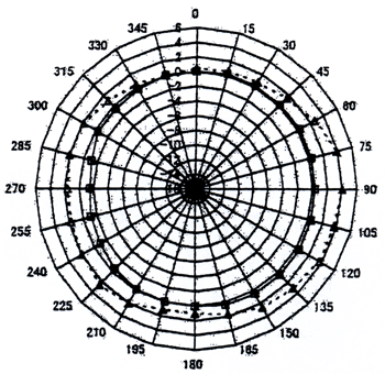
Directivity of the SART with circular polarization
antenna Azimuth pattern in horizontal plane
Gain in vertical polarization: 1.5 to +0.5 dBi
Gain in horizontal polarization: 0 to +4.0 dBi |
The SART used in this study has a helical antenna (See Figure-1) which radiates a radio wave in circular polarization. Figure-2 shows the directivity of the helical antenna in the horizontal plane against horizontal and vertical polarization. The SART was used in a series of tank tests and on-sea trials. In addition, a existing SART which antenna polarization is horizontal was used for a comparison purpose.
Measurement of received power of SART signal and observation of visibility of the signal on radar screen were carried out in various water-wave conditions at a test tank of Tokyo University of Merchant Marine. The results are as follows.
.1 A strong interference caused by the signal reflected at the water surface was observed for SART signal of horizontal polarization where the water-wave height is low. In this case, interruption of SART signal was also observed sometimes.
.2 Any strong interference caused by the signal reflected at the water surface was observed for SART signal of circular polarization where the water-wave height is low. In this case, interruption of SART signal was not observed.
.3 There no significant difference on observation between SART signal of horizontal polarization and circular polarization when water-wave height is rather high.
These results lead us to a conclusion that the circular polarization is superior to the horizontal polarization for SART.
On-sea trials were conducted on December 14th 2000 in cooperation of ships and aircrafts of Maritime Authorities of Japan in Sagami Bay to observe visibility of the SART signal on the radars on board the ships and the aircrafts. In the mean time, the received power of the SART signal was measured by a land-based radar. The following results have been obtained.
3.1 Observation by aircraft radar
The SART signal of circular polarization was observed stably on PPI of the aircraft radars. The maximum visible distance of SART signal of circular polarization was 37 NM, while that of horizontal polarization was 30 NM. This confirms the superiority of circular polarization.
3.2 Observation by marine radar
Table-1 shows the results of the observation of the SART signals on marine radars equipped on vessels. The antenna height of both SARTs was 1 m from the sea level. The maximum visible distance of SART signal of circular polarization was 14 NM, while that of horizontal polarization was 11.5 NM. These results confirm the superiority of circular polarization.
| Table-1 Comparison of visibility of SART signals
of circular polarization and horizontal polarization |
| Distance(NM) |
Results of observation of SART signal
of horizontal polarization |
Results of observation of SART signal
of circular polarization |
| 14.0 |
Could not observed |
Observed with
steady gaze |
| 12.8 |
Could not observed |
Observed but weak |
| 12.1 |
Could not observed |
Observed almost
clearly |
| 11.5 |
Faintly observed |
Observed clearly |
| 10.5 |
Slightly observed |
Observed clearly |
| 9.4 |
Slightly observed |
Observed clearly |
| 9.1 |
Observed, but
sometimes slightly |
Observed clearly |
| 8.6 |
Observed clearly |
Observed clearly |
| 7.5 |
Observed clearly |
Observed clearly |
| 5.0 |
Observed clearly
(Escorting vessel could be seen.) |
Observed clearly
(Escorting vessel could be seen.) |
| 1.8 |
SART signal on
PI started becoming circular. |
Observed clearly
(Escorting vessel could be seen.) |
| 1.5 |
SART signal on
PPI was totally circular. |
SART signal on
PPI started becoming circular. |
| 0.9 |
SART signal on
PPI was totally circular. |
SART signal on
PPI was totally circular. |
| 0.4 |
SART signal on
PPI was totally circular. |
SART signal on
PPI was totally circular. |
|
3.3 Observation and measurement by land-based radar
A 9GHz radar of research purpose owned by Tokyo University of Merchant Marine installed on a vehicle was used to observe and measure the SART signal of circular polarization. The radar was set at a shore. The SART was moved on sea by a escorting small vessel. The antenna height of the SART was kept 1m from the sea level. The distance between the radar and the SART was changed. The received power of the SART was measured by the radar.
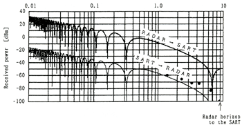
Figire-3 shows the calculation of received power of SART signal of horizontal polarization and measured results of received power of SART signal of circular polarization. The calculation was based on the assumption that reflectivity of SART signal at sea surface is 1, and phase change at the reflection is pi radian.
The measured value of received power of SART signal of circular polarization was, in any case, stronger than the calculated value of SART signal of horizontal polarization See Figure-3. The black circle marks are the measured value of SART signal of circular polarization. The measured values always appear above the calculated curve for "SART to radar".
Reason of this measurement results can be considered as follows. The SART signal of circular polarization changes continuously the polarization plane in 360 degrees. Therefore, the phase change at the sea surface is not constant. This results in the fact that the compensation happened at mixture of direct wave and reflected wave is not constant and the radar can receive the maximum power of the mixture. Then, this fact leads the extension of the maximum visible distance of SART of circular polarization, even though there is a fundamental loss (by 3 dB) shall happen when radar antenna of horizontal polarization receives SART signals of circular polarization.
Appearance of SART signal of circular polarization on the radar PPI was stronger and clearer than that of horizontal polarization.
Radar ( Peak power : 25 kW Antenna height : 9.5m )
SART ( Peak power : 400 mW Antenna height : 1.0m )
| (拡大画面:59KB) |

Figure 3 The radar's received power of the SART signal,
( Curves show the calculated values in case
of the horizontal polarization antanna SART
according to the radar transponder equation,
and dotts show the observed values in case of the
circular polarization antenna
SART. ) |
|