参考資料2
| S&R-2160 |
MODELING OF RISER RESPONSE FOR DP CONTROL
|
| |
Bert J. leira, Qiaofeng Chen, Asgeir Sorensen, Carl M. Larsen |
| PIPE-4116 |
EXPERIMENTAL ESTIMATION OF PHYSICAL PROPERTIES OF A FLEXIBLE RISER
|
| |
Carlos magluta, Ney Roitman, paula F Viero, Luiz F. L. Rose, |
| |
Elton J. B. Ribeiro |
| OFT-5102 |
DYNAMIC POSITIONING SYSTEM OF OFFSHORE PLATFORM BY ADVANCED CONTROL |
| |
Ikuo Yamamoto, Masami Matsuura, Hiroaki Hirayama, |
| |
Norihiko Okamoto |
OMAE2001/S&R-2160
Proceedings of OMAE'01
20th International Conference on Offshore Mechanics and Arctic Engineering
June 3 - 8, 2001, Rio de Janeiro, Brazil
MODELING OF RISER RESPONSE FOR DP CONTROL
Bernt J. Leira NTNU, Faculty of Marine Technology N-7491 Trondheim, Norway
Asgeir Sorensen NTNU, Faculty of Marine Technology N-7491 Trondheim, Norway
Qiaofeng Chen NTNU, Faculty of Marine Technology N-7491 Trondheim, Norway
Carl M. Larsen NTNU, Faculty of Marine Technology N-7491 Trondheim, Norway
ABSTRACT
The present paper is concerned with modeling or riser response to static and dynamic loading. Focus is on top and bottom angles which are of crucial importance e.g. during drilling and workover operations. Parametric studies are performed for a representative deep-water riser configuration. The relationship between surface floater motion and angle responses is investigated. In a wider context, the possibility of reducing the maximum response levels by dynamic positioning of the floater is the main objective. It is illustrated by a numerical simulation of the system behavior how the response relations obtained herein can be utilized for such a purpose.
Generally, minimization of one of the riser end angles by adjusting the vessel position can only take place at the cost of increasing the other one. Hence, an optimum position should be defined by considering both angles but with different weight functions. An attractive approach is to determine these weights as functions of the respective reliability indices for each of the two angles. The viability of this scheme is also explored by numerical simulation for the same example riser configuration.
INTRODUCTION
Several problems have been encountered during drilling operations due to excessive top and bottom risers angle response levels. For the upper part or the riser. contact between the riser pipe and the surface vessel (e.g. the moonpol) may easily lead to serious damage. For the lower part. even moderate angles (2-4°)may imply that the drill-pipe within the riser gets into contact with the ball-joint or well-head. Wear due to metal-to-metal contact implies that damage to the well-head may occur over time, and in some cases a blow-out at the seabed can be the final result. For large riser angles (>4-6°) at the seabed. the operation has to be interrupted and for increasingly larger angles (>6-7°) a controlled disconnect of the lower part of the riser must be performed. If the bottom angle increases too quickly. an emergency disconnect is activated automatically on many installations. If these safety components do not work properly, the subsea components will generally have to be replaced due to serious damage.
It is accordingly of interest to minimize the response levels for the riser angles. One way of achieving this is by moving the surface floater to a given position. If mooring lines are applied. this can only be performed at certain intervals. If a dynamic positioning (DP) system is applied, the attractive option arises to implement riser response criteria within the control loop. See e. g. Balchen et al.,(1980), Sorensen et al. (1996) and Sorensen et al.(2000b) for a description of presently implemented algorithms. Extended algorithms accounting for criteria based on riser response have been investigated e.g. in Imakita et al (2000) and Sorensen et al. (2000a). At present, it seems that no such systems have been implemented on an offshore drilling unit. For any such system. control of the wave-frequency motions or the vessel is unrealistic. Instead. it is aimed at controlling the slowly varying low-frequency (LF) motions from wind, wave forces and current variations.
A basic problem is that minimizing the response level for one of the angles will typically imply that the response level for the other angle increases (somewhat depending on the current profile as a function of depth). Accordingly. relative weights must be put on the criteria for the top versus the bottom angle. An attractive approach is to express these weights as functions of the respective reliability indices for each of the two angles. The viability of this scheme is also explored by numerical simulation for an example riser configuration operating at a water depth or 1000m.
GENERAL FRAMEWORK FOR CONTROL OF RISER RESPONSE BASED ON DYNAMIC POSITIONING
Background
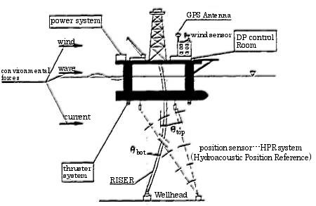
A general view of a vessel-riser system is shown in Figure 1. In order to implement riser response criteria within a dynamic positioning control loop, a description of the presently operating control schemes is first required. Such control schemes are typically based on a fixed set-point which is the target position of surface vessel. Frequently, this set-point is taken to be the position right above the well-head. If criteria related to riser response are to be included, this set-point will move as a function of the current velocity, the slow-drift vessel motion and also other parameters such as mud weight and riser top tension. Such a procedure may conveniently be referred to as "set-point chasing". which implies a higher degree of flexibility in the control algorithm (Sorensen et a)., 2000b).
Figure 1. General view of the floater-riser System
Control Algorithm
Control of the ship motion is based on the dynamic equilibrium equation for ship motion including the effect or the control actions. Like conventional marine vessels, a DP vessel is subjected to time-varying environmental forces (waves. wind and current). But for a DP vessel, it is not desirable to counteract the wave-frequency (WF) movement (small) amplitude oscillating motion) caused by first-Order wave loads. This is due to compensation of the WF components of the motion requiring excessive thruster modulation. The control action of the propulsion system of a DP vessel is activated by the LF part of the vessel movement caused by current, wind and second mean and slowly varying wave loads.
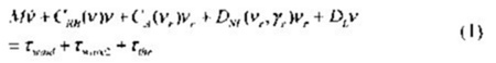
The 3 degrees of freedom (DOF) nonlinear LF body-fixed coupled equations of motion in surge, sway and yaw of the DP vessel can be formulated as:
where ν is the velocity vector, expressed as ν = [u,ν,r]T. νr is the relative vector including the effect of current. The generalized controlling force is contained in the last term on the right-hand side, i.e. the thruster force τthr. This generalized force will be different at each time step according to whether riser angle criteria are taken into account or not.
Note that the dynamic influence on the vessel due to the riser is assumed to be negligible. Also since only LF motion is considered here, asymptotic values of added mass for frequencies approaching zero can be used.
The various matrices occurring on the left hand side of the equilibrium equation are briefly discussed below. The kinematics arc as formulated in Sorensen et al. (2000b) with the origin of the body-fixed system located in the center of gravity with the x-axis positive forwards, the y-axis positive to the starboard and the z-axis positive downwards.
Mass Matrix
M is the mass matrix including added mass, expressed as:
where m is the vessel mass, Iz is the moment of inertia about the z-axis. The terms -Xu-Yv and -Nr are the zero-frequency added mass in surge, sway and yaw.
Skew-symmetric Coriolis and Centripetal Matrix
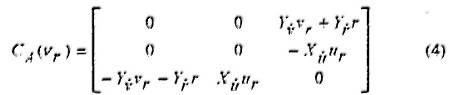
The skew-symmetric Coriolis and centripetal matrix of the vessel can be formulated as:
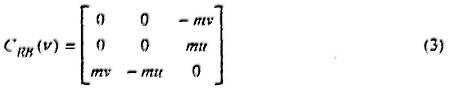 The skew-symmetric Coriolis matrix due to the potential part of the current is modelled as:
The motivations for the skew-symmetric formulation of. Coriolis terms are to achieve a compact notation and to demonstrate stability in certain applications (Fossen 1994). It should be noted that for small velocities CRB(ν)and CA(νr) are very small and can be neglected.
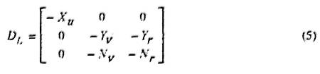
Linear Damping Matrix:
The damping matrix DL is caused by linear wave drift damping and laminar skin friction damping. This matrix is expressed as:
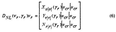
Nonlinear Damping Vector:
The nonlinear damping vector for the semi-submersible is formulated as:
where ucr is the magnitude of the resultant vector for the two basic components ur and vr In equation (6), Xu|u|(γr), Yv|v| (γr) and Nr|r|(γr) are the drag coefficients in surge. sway and yaw respectively. These coefficients can either be found by model tests or computed by dedicated and well-recognized software packages. They are generally function of the relative angle between the current velocity and the vessel velocity. γr.
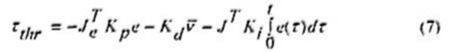
PID Control Law
Many DP systems rely on multivariable proportional-integral-differential (PID) algorithms in conjunction with an observer providing state estimates. The basic principle of a PID control law is to generate a thrust which has the components proportional to the 3-dimensional position and heading deviation vector 'e' in the vessel's location (the proportional term), velocity deviation vector 'e' (the differential term), and to the accumulated deviation vector (the integral term). all at time t. Based on this principle, the required thruster force vector τthr in the body-fixed frame can be formulated as:
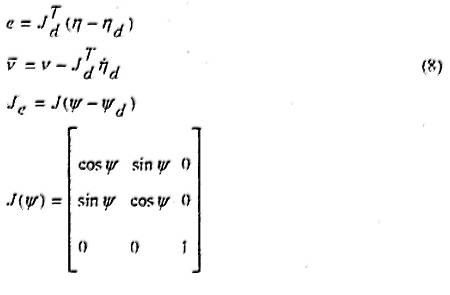
Here, the following quantities are employed:
where J-1=J, J-1d=J1d. The 3-dimensional vector ηd defines the desired earth-fixed position and heading coordinates. Κp, Κd and Ki are the 3x3 non-negative controller gain matrices that will be discussed in the next section. η and ν are the actual position and velocity vectors of the vessel.
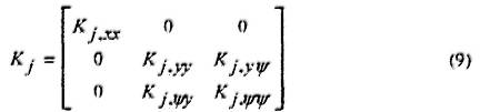
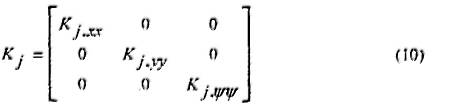
It should be noted that the multivariable 3x3 non-negative controller gain matrices Κp, Κd and Κi are matrices having the form:
where subscript 'j' stands for the subscripts 'p, d, i' of the controller gain matrices. The terms of Κj-yΨ and Κj-Ψy are due to the coupled forces for actuating the motion of the vessel in sway and yaw. The coupling effect between motion of sway and yaw is neglected without loss of accuracy. The controller gain matrices accordingly become diagonal matrices:
One should notice that we have assumed that all the states are available. This is not true in general. However. by introducing an observer state, estimates can be calculated. see Fossen (1994). However, as the main objective in this work is to demonstrate the optimal setpoint chasing, we have. for simplicity. assumed full state feedback. It is believed that this simplification will have no impact on the conclusions made.
Optimal Position Accounting for Riser Angle Criteria
For optimal setpoint chasing. where the vessel moves from one position and heading to another, a reference model is needed for achieving a smooth transition. The reference generates smooth reference trajectories for the vessel to follow.
The optimal position of the vessel, ηopt, can be computed by taking the riser angle criteria into account. based on the measured values of the angles at any time. However, the vessel can not be moved to the specified optimal position instantaneously. Instead, a smooth transition is required. Therefore, the adjusted position and heading ηd can be obtained if a reference model for ηopt is introduced. In order to provide high-performance of the DP vessel's operations. a third-order reference model is usually chosen, see Sorensen et al. (1996).
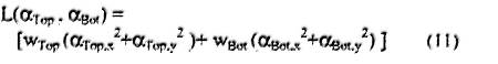
Disregarding the riser angles. the optimal position is typically taken to be just above the well-head. This will not be the case if criteria related to the riser angles are included. This can be achieved by introducing a quadratic loss function based on the top and bottom angles, which is of the type:
where (αTop,x, αTop,y) are the x- and y-components of the top angle, (αBot,x, αBot,y) are the x- and y-components of the bottom angle, and WTop and WBpt are the corresponding weighting factors.
The angular components in this expression can in term be expressed as the sum of the instantaneous measured angle components and the incremental angle components due to an increment of the vessel position. The angular incremental components are in turn expressed as explicit functions of this incremental vessel position by means of the influence coefficients. These four influence coefficients (αTop,x, αTop,y) and(αBot,x, αBot,y) are basically obtained from a numerical model of the riser. such as a Finite Element Model.
These coefficients represent the change of each angle component given a unit change (i.e. 1 m) of the vessel position. In principle. these coefficients will change as functions of the vessel position due to the nonlinear geometric behaviour of the riser. They will also change if the riser top tension changes. Furthermore, they can be anticipated to change as functions of the surface current velocity and the current profile (i.e. the velocity variation as a function of depth).
Accordingly, these coefficients should be calculated at each time step based on a pre-established riser model which is subjected to the proper static loads at that step. However. significant savings in computational effort can be achieved if these coefficients can be established in advance, such that evaluation of these at each time step is avoided. This possibility obviously depends on the stability of these coefficients for varying vessel offset and varying current (assuming that the riser weight and top tension is constant). These coefficients will be addressed in the next section.
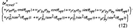
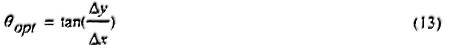
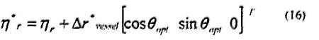
Having established these coefficients, the optimal increment of the vessel position and the optimal direction of this increment can be found by differentiating the loss function with respect to these quantities. By setting the derivatives equal to zero, the minimum value of the loss function is hence identified. The optimal increment of vessel position is found to be:
and the corresponding optimal direction is given by:
where
Here, (αtx, αry) are the x-and y-components of the measured top angle, and the corresponding components for the measured bottom angle are designated as (αbx ,αby). The optimal vessel position setpoint becomes: