10 Specification of environmental testing for the device
10.1 Analytes
| Analyte |
CAS Nos. |
| Nitrogen Oxides (Nox) |
10102-44-0 (NO2), 10024-
97-2(NO) |
10.2 Applicability
10.2.1 This specification is for evaluating the acceptability of NOx continuous emission monitoring systems (CEMS) at the time of installation or soon after and whenever specified in the regulations.
10.2.2 This specification is not designed to evaluate the installed CEMS performance over an extended period of time nor does it identify specific calibration techniques and other auxiliary procedures to assess the CEMS performance. The vessel owner or operator is responsible to calibrate, maintain, and operate the CEMS properly. The Administration may require the operator to conduct CEMS performance evaluations at other times besides the initial test to evaluate the CEMS performance.
10.3 Summary of performance specification
Procedures for measuring CEMS relative accuracy and calibration drift are outlined. CEMS installation and measurement location specifications, equipment specifications, performance specifications, and data reduction procedures are included. Conformance of the CEMS with the performance specification is determined.
10.4 Definitions
10.4.1 Calibration drift (CD) means the difference in the CEMS output readings from the established reference value after a stated period of operation during which no unscheduled maintenance, repair, or adjustment took place.
10.4.2 Centroidal area means a concentric area that is geometrically similar to the stack or duct cross section and is no greater than I percent of the stack or duct cross-sectional area.
10.4.3 Continuous emission monitoring system means the total equipment required for the determination of a gas concentration or emission rate. The sample interface, pollutant analyzer, diluent analyzer, and data recorder are the major subsystems of the CEMS.
10.4.4 Data recorder means that portion of the CEMS that provides a permanent record of the analyzer output. The data recorder may include automatic data reduction capabilities.
10.4.5 Diluent analyzer means that portion of the CEMS that senses the diluent gas and generates an output proportional to the gas concentration.
10.4.6 Path CEMS means a CEMS that measures the gas concentration along a path greater than 10% of the equivalent diameter of the stack or duct cross section.
10.4.7 Point CEMS means a CEMS that measures the gas concentration either at a single point or along a path equal to or less than 10 per cent of the equivalent diameter of the stack or duct cross section.
10.4.8 Pollutant analyzer means that portion of the CEMS that senses the pollutant gas and generates an output proportional to the gas concentration.
10.4.9 Relative accuracy (RA) means the absolute mean difference between the gas concentration or emission rate determined by the CEMS and the value determined by the reference method (RM), plus the [2.5% error] confidence coefficient of a series of tests, divided by the mean of the RM tests or the applicable emission limit.
10.4.10 Sample interface means that portion of the CEMS used for one or more of the following: sample acquisition, sample delivery, sample conditioning, or protection of the monitor from the effects of the stack effluent.
10.4.11 Span value means the concentration specified for the affected engine category in an applicable subpart of the regulations that is used to set the calibration gas concentration and in determining calibration drift.
10.5 Safety
The procedures under this performance specification may involve hazardous materials, operations, and equipment. This performance specification may not address all of the safety problems associated with these procedures. It is the responsibility of the user to establish appropriate safety and health practices and determine the applicable regulatory limitations prior to performing these procedures. The CEMS user's manual and materials recommended by the reference method should be consulted for specific precautions to be taken.
10.6 Equipment and supplies
10.6.1 CEMS equipment specifications
10.6.1.1 Data recorder scale. The CEMS data recorder output range should include zero and a high-level value. The high-level value is chosen by the vessel owner or operator and is defined as follows:
| |
.1 |
|
For a CEMS intended to measure an uncontrolled emission, the high-level value should be between 1.25 and 2 times the maximum potential emission level over the appropriate averaging time, unless otherwise specified by the Administration.
|
| |
.2 |
|
For a CEMS installed to measure controlled emissions or emissions that are in compliance with an applicable regulation, the high-level value between 1.5 times the pollutant concentration corresponding to the emission standard level and the span value given in the applicable regulations is adequate.
|
| |
.3 |
|
Alternative high level values may be used.
|
| |
.4 |
|
If an analogue data recorder is used, the data recorder output should be established so that the high-level value would read between 90 and 100% of the data recorder full scale. (This scale requirement may not be applicable to digital data recorders.) The zero and high level calibration gas, optical filter, or cell values should be used to establish the data recorder scale. |
10.6.1.2 The CEMS design should also allow the determination of calibration drift at the zero and high-level values. If this is not possible or practical, the design should allow these determinations to be conducted at a low-level value (zero to 20% of the high-level value) and at a value between 50 and 100% of the high-level value. In special cases, the Administration may approve a single-point calibration-drift determination.
10.6.2 Other equipment and supplies, as needed by the applicable reference method(s), may be required.
10.7 Reagents and standards
10.7.1 Reference gases, gas cells or optical filters. As specified by the CEMS manufacturer for calibration of the CEMS (these need not be certified).
10.7.2 Reagents and standards. May be required as needed by the applicable reference method(s) (see Section 8.4.2 of this Performance Specification).
10.8 Performance specification test procedure
10.8.1 Installation and measurement location specifications
10.8.1.1 CEMS installation. Install the CEMS at an accessible location where the pollutant concentration or emission rate measurements are directly representative or can be corrected so as to be representative of the total emissions from the engine or at the measurement location cross section. Then select representative measurement points or paths for monitoring in locations that the CEMS will pass the RA test (see Section 4.8.4). If the cause of failure to meet the RA test is determined to be the measurement location and a satisfactory correction technique cannot be established, the Administration may require the CEMS to be relocated. Suggested measurement locations and points or paths that are most likely to provide data that will meet the RA requirements are listed below.
10.8.1.2 CEMS measurement location. It is suggested that the measurement location be (1) at least two equivalent diameters downstream from the nearest control device, the point of pollutant generation, or other point at which a change in the pollutant concentration or emission rate may occur and (2) at least a half equivalent diameter upstream from the effluent exhaust or control device.
10.8.1.2.1 Point CEMS. It is suggested that the measurement point be (1) no less than 1.0 m (3 .3 ft) from the stack or duct wall or (2) within or centrally located over the centroidal area of the stack or duct cross section.
10.8.1.2.2 Path CEMS. It is suggested that the effective measurement path (1) be totally within the inner area bounded by a line 1.0 m (3.3 ft) from the stack or duct wall, or (2) have at least 70% of the path within the inner 50% of the stack or duct cross-sectional area, or (3) be centrally located over any part of the centroidal area.
10.8.1.3 Reference method measurement location
10.8.1.3.1 Select as appropriate an accessible RM measurement point
10.8.2 Pretest preparation. Install the CEMS, prepare the RM test site according to the specifications in Section 4.8,1, and prepare the CEMS for operation according to the manufacturer's written instructions.
10.8.3 Calibration drift test procedure
10.8.3.1 CD Test Period. [to be developed]
10.8.3.2 The purpose of the CD measurement is to verify the ability of the CEMS to conform to the established CEMS calibration used for determining the emission concentration or emission rate. Therefore, if periodic automatic or manual adjustments are made to the CEMS zero and calibration settings, conduct the CD test immediately before these adjustments, or conduct it in such a way that the CD can be determined.
10.8.3.3 Conduct the CD test at the two points specified in Section 4.6.1.2. Introduce to the CEMS the reference gases, gas cells, or optical filters (these need not be certified). Record the CEMS response and subtract this value from the reference value.
10.8.4 Relative accuracy test procedure
10.8.4.1 RA test period. [to be determined]
10.8.4.2 Reference methods. [to be determined]
10.8.4.3 Sampling strategy for RM tests. [to be determined]
10.8.4.4 Number of RM tests. Conduct a minimum of nine sets of all necessary RM test runs. NOTE: More than nine sets of RM tests may be performed. If this option is chosen, a maximum of three sets of the test results may be rejected so long as the total number of test results used to determine the RA is greater than or equal to nine. However, all data should be reported, including the rejected data.
10.8.4.5 Correlation of RM and CEMS data. Correlate the CEMS and the RM test data as to the time and duration by first determining from the CEMS final output (the one used for reporting) the integrated average pollutant concentration or emission rate for each pollutant RM test period. Consider system response time, if important, and confirm that the pair of results are on a consistent moisture, temperature, and diluent concentration basis. Then, compare each integrated CEMS value against the corresponding average RM value. Use the following guidelines to make these comparisons.
10.8.4.6 Calculate the mean difference between the RM and CEMS values in the units of the emission standard, the standard deviation, the confidence coefficient, and the relative accuracy according to the procedures in Section 4.10.0.
10.8.5 Reporting
10.9 Analytical procedure
Sample collection and analysis are concurrent for this performance specification (see Section 8.0). Refer to the RM for specific analytical procedures.
10.10 Calculations and data analysis
10.10.1 Summarize the results on a data sheet (to be developed).
10.10.2 All data from the RM and CEMS.
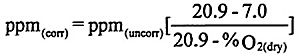
10.10.2.1 Correction to units of standard (as applicable)
10.10.2.1.1 Correct to diluent basis.
10.10.2.1.2 The following is an example of mass/gross calorific value (lbs/million BTU) correction.
lbs/MMBtu=Conc(dry) (F-factor) (20.9/20.9- %O2)
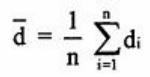
10.10.3 Arithmetic mean. Calculate the arithmetic mean of the difference, d, of a data set as follows:
where:
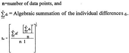
10.10.4 Standard deviation. Calculate the standard deviation Sd:
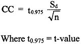
10.10.5 Confidence coefficient. Calculate the [2.5%] confidence coefficient (one-tailed), CC, as follows:
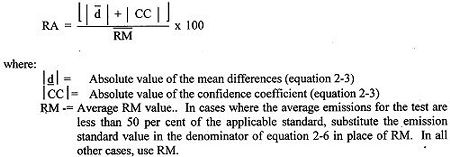
10.10.6 Relative accuracy. Calculate the RA of a set of data as follows:
10.11 Method performance
10.11.1 Calibration drift performance specification. The CEMS calibration should not drift or deviate from the reference value of the gas cylinder, gas cell, or optical filter by more than 2.5 per cent of the span value. If the CEMS includes pollutant and diluent monitors, the CD should be determined separately for each in terms of concentrations (See Performance Specification 3 for the diluent specifications), and none of the CDs should exceed the specification.
10.11.2 Relative accuracy performance specification. The RA of the CEMS should be no greater than 20% when is used in the denominator of Eq. 2-6 (average emissions during test are greater than 50% of the emission standard) or 10% when the applicable emission standard is used in the denominator of Eq. 2-6 (average emissions during test are less than 50% of the emission standard).
10.11.3 For instruments that use common components to measure more than one effluent gas constituent, all channels should simultaneously pass the RA requirement, unless it can be demonstrated that any adjustments made to one channel did not affect the others.
10.12 Alternative procedures
10.12.1 The criteria for which the reference method procedure for determining relative accuracy (see Section 8.4 of this performance specification) may be waived and the following procedure substituted under the following conditions [need something more here].
10.12.2 Conduct a complete CEMS status check following the manufacturer's written instructions. The check should include operation of the light source, signal receiver, timing mechanism functions, data acquisition and data reduction functions, data recorders, mechanically operated functions (mirror movements, zero pipe operation, calibration gas valve operations, etc.), sample filters, sample line heaters, moisture traps, and other related functions of the CEMS, as applicable. All parts of the CEMS should be functioning properly before proceeding to the alternative RA procedure.
10.12.3 Alternative RA procedure.
10.12.3.1 Challenge each monitor (both pollutant and diluent, if applicable) with cylinder gases of known concentrations or calibration cells that produce known responses at two measurement points within the ranges shown in Table 2-2.
10.12.3.2 Use a separate cylinder gas (for point CEMS only) or calibration cell (for path CEMS or where compressed gas cylinders can not be used) for measurement points 1 and 2. Challenge the CEMS and record the responses three times at each measurement point. The Administration may allow dilution of cylinder gas using the performance criteria [to be completed]. Use the average of the three responses in determining relative accuracy.
10.12.3.3 Operate each monitor in its normal sampling mode as nearly as possible. When using cylinder gases, pass the cylinder gas through all filters, scrubbers, conditioners, and other monitor components used during normal sampling and as much of the sampling probe as practical. When using calibration cells, the CEMS components used in the normal sampling mode should not be by-passed during the RA determination. These include light sources, lenses, detectors, and reference cells. The CEMS should be challenged at each measurement point for a sufficient period of time to assure adsorption-desorption reactions on the CEMS surfaces have stabilized.
10.12.3.4 Use cylinder gases that have been certified by [to be completed]
10.12.3.5 Use calibration cells certified by the manufacturer to produce a known response in the CEMS. The cell certification procedure should include determination of CEMS response produced by the calibration cell in direct comparison with measurement of gases of known concentration. This can be accomplished using SRM or CRM gases in a laboratory source simulator or through extended tests using reference methods at the CEMS location in the exhaust stack. The calibration cell certification procedure should be subject to approval of the Administration.
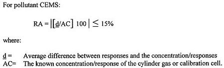
10.12.4 The differences between the known concentrations of the cylinder gases and the concentrations indicated by the CEMS are used to assess the accuracy of the CEMS. The calculations and limits of acceptable relative accuracy are as follows:
NOTE: Waiver of the relative accuracy test in favor of the alternative RA procedure does not preclude the requirements to complete the CD tests nor any other requirements specified in an applicable subpart for reporting CEMS data and performing CEMS drift checks or audits.