ANNEX 1
PROPOSALS
JAPAN PROPOSAL
The draft Guidelines for On-board NOx Monitoring and Recording Devices
1 Definition of continuous NOx monitoring
1.1 General
Continuous NOx monitoring for certification survey shall be made at least five times within the last 30 days before the periodic and intermediate surveys at the most frequently used load point during NOx monitoring. Each measuring time shall be continued at least for 30 minutes. However, if there is rational reason for inability to take measurements within 30 days, measurement data taken within six months before the certification survey shall be permitted. (Note : Development is being proceeded for NOx monitoring starting after the previous periodic or intermediate survey until 30 days before the next survey.)
1.2 Specifications of NOx monitoring and recording devices
1.2.1 General
| |
.1 |
|
A device for on-board continuous measurement and recording exhaust gas components during ship operation is used as an equipment to monitor and record NOx, and it shall have sufficient mechanical strength against vibration and shock, where the measurement value for the accuracy (repeatability) is not effected by.
|
| |
.2 |
|
The device for monitoring and recording NOx are likely to have limitations in handling, posting of engineers, acquirement of related test instrument and so on, when compared with those of the device for land measurement of exhaust gas components. Due to this reason, a device with simple handling and maintenance, with reliable performance and function shall be used.
|
| |
.3 |
|
A device for on-board continuous measurement and recording of exhaust gas components during ship operation is used as an equipment to monitor and record NOx, where ambient conditions (temperature, humidity, power supply fluctuation, etc.) during measurement and skill capability of operator are put into consideration, which the function and performance are approved by the Administration based on this guideline.
|
| |
.4 |
|
The analyzer used for NOx monitoring shall have a measurable range for precision concentration measurement. All analyzers shall be capable of continuous measurement from any gas stream, which can be output for continuous recording. It is recommended that the analyzers shall be operated such that the measured concentration fall between 15% and 100% of full scale.
|
| |
.5 |
|
The electromagnetic compatibility (EMC) of the device shall be set so that additional errors can be minimized. |
1.2.2 Gas drying
The effect of the optional gas drying device on the concentration of the measured gases shall be minimum. Chemical dryers are not an acceptable method of removing water from the sample.
1.2.3 Specifications of analysers
The gas for NOx monitoring shall be analyzed, using the analyzer described below. For a non linear analyzers, the use of linearizing circuits is permitted.
| |
.1 |
|
Oxygen analyzer (O2 analyzer)
The oxygen analyzer shall be of a paramagnetic detector (PMD), a zirconium dioxide (ZRDO) sensor or an electrochemical (ECS) sensor. Note: The interference of CO2 and NOx shall be compensated in the electrochemical sensor.
|
| |
.2 |
|
Nitrogen oxide analyzer (NOx analyzer)
The nitrogen oxide analyzer, measured on a dry basis, shall be of a chemiluminescent detector (CLD) equipped with a nitrogen dioxide and monoxide converter, an electrochemical sensor (ECS), a zirconium dioxide sensor (ZRNOXD) or a heated chemiluminescent detector (HCLD). If the detector is equipped with nitrogen dioxide (NO2) and monoxide (NO) conversion function, or measures NO and NO2 simultaneously or independently, the NO2/NO converter may be unnecessary. If measured on a wet basis, the HCLD with converter maintained at above 333k (60℃) or a heated zirconium dioxide sensor shall be used. However, a water quench check (refer to test item 8 of table 2 of Reference document 1 in this guideline) shall be satisfied. |
1.2.4 Specifications of recording devices
The measurement data during NOx monitoring shall be recorded, using the following recording devices.
1.2.4.1 Electromagnetic recording device
| |
.1 |
|
The device shall be capable of recording the date and time of measurement and the measured values and printing out the information.
|
| |
.2 |
|
The data sampling frequency shall be above once per minute. |
1.2.4.2 Strip chart recorder
| |
.1 |
|
The effective recording width shall be at least 100mm.
|
| |
.2 |
|
The strip chart recorder shall be capable of selecting the chart speeds of minimum of 20 mm/hour to above 20 mm/min. |
1.2.4.3 Other recording devices
The device shall have functions equivalent to those of the electromagnetic recording device or the strip chart recorder.
2 Data recording, processing and retention
The concentration of the exhaust gas shall be recorded, using recording devices specified in 1.2. The data shall be adequately processed and retained. Records of the relevant engine performance and zero/span check, and other data shall also be recorded and retained.
3 Specifications for the equipment to ensure that its reliability is maintained during service
If the NOx analyzer calibrated on land is performing the zero/span check on-board, the analyzer reliability is regarded as maintained. (Note: the zero/span check method is under development.)
3.1 General
As a means to ensure that the reliability of the analyzer is maintained, the zero/span check and periodic calibration of the analyzer shall be made. (Note: The zero/span check method and the intervals of periodic calibration of analyzers are under development.)
3.2 Periodical calibration of the analyzers
3.2.1 Repeatability
The repeatability of the analyzer shall be within ±2% of full scale.
3.2.2 Measurement error (Linearity error)
The measurement error of an analyzer shall be within ±5% of full scale.
4 Specifications for environmental testing of the device
For details of environmental testing of the analyzer and recording device, description in IACS UR E10 shall be observed.
5 Specifications for the testing of the analyzer to demonstrate that it has a suitable accuracy, repeatability and cross sensitivity compared with the applicable sections of this Code
The testing conditions, testing method and criteria concerning the testing of the analyzer to demonstrate that it has a suitable accuracy, repeatability and cross sensitivity are shown in Reference document 1.
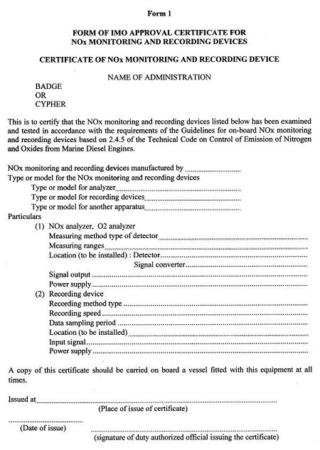
6 Form of the approval certificate to be issued by the Administration
The style of the document format of the approval certificate of the analyzer and recording device (issued to the device which has passed the environmental and performance tests of manufacturer's factory of measuring instruments specified in 4 and 5) is shown in Form 1.
Reference document 1
Performance test of analyzer at equipment manufacturing factory, etc.
1 Test conditions
The performance test conditions of the analyzer are as follows.
| |
(1) |
|
Ambient temperature: Temperature between 5 and 35℃, fluctuation within ±5℃ |
| |
(2) |
|
Humidity: Relative humidity within 85% |
| |
(3) |
|
Atmospheric pressure: 95 to 106 kPa (950 to 1060 mbar), with fluctuation within 5% |
| |
(4) |
|
Power supply voltage: Rated voltage |
| |
(5) |
|
Power supply frequency: Rated frequency |
| |
(6) |
|
Warm-up time: Time described in operation manual |
| |
(7) |
|
Gas used for test: Standard gas, span gas, zero gas, and nitrogen monoxide.
The type of gas and applicable test item are as per Table 1. |
Table 1
| Type of gas |
Component concentration (Balance gas: N2) |
Applicable test item |
| Standard Gas |
Span gas |
Concentration of 80 to 100 % of each range |
5, 8 |
| Intermediate point gas |
Concentration of approx. 50 % of each range |
5 |
| Zero gas |
Concentration of 0% of each range |
5, 8 |
| * In the case of zirconium dioxide type 02 analyzer, concentration of 10 to 15% of each range may be used. |
| Nitrogen dioxide |
Concentration of 10% of each range |
6 |
| Gas for span adjustment |
Concentration of 80 to 95% of each range |
2, 4, 7, 9, 10 |
| Gas for zero adjustment |
Concentration of 0% of each range |
2, 3, 4, 7 |
| * In the case of zirconium dioxide type 02 analyzer, concentration of 10 to 15% of each range may be used. |
| Note 1 : |
Concentration of the gas for span and zero adjustment must be checked against the standard gas.
|
| Note 2: |
Nitrogen dioxide is the gas for testing the NO2-NO conversion error of the nitrogen oxide (NOx) analyzer. |
2. Performance test
The test items, test conditions, components and criteria are as per Table 2.
Table 2
| Test item |
Test conditions and test method |
Criteria |
1.
Construction
Test
|
(1) The device is in correct shape. The assembly and the
finish of each part are good and rigid.
(2) There is no readily possibility of danger durning normal
operation. The operation can be done safely and smoothly.
(3) Structure of each part is free from volnntary mechanical
or electrical failures, or danger.
(4) The device is structured so that it does not allow to cause
trouble during operation due to dew.
(5) Parts in contact with light sources, heaters and other heat
generating parts are structured so that they do not allow
thermal deformation or functional changes.
(6) The device is structured so that maintenance work and
inspection can be done safely. |
To meet
each
requirement |
2.
Repeatability |
At the measuring ranges to be used,
supply the gas for zero adjsutment to the analyzer at the
specified flow rate and then supply the gas for span
adjsutment with the same condition, after checking the final
value using a recorder or the like. Repeat the procedure three
times and calculate the average of each value for zero and
span to determine the precentage of the difference of the average value and the highest value. |
Within
±2% of
full scale |
3.
Zero drift |
At the measuring ranges to be used,
supply the gas for zero adjsutment to the specified flow rate
and execute continuous measurement for 24 hours.
Obtain the percentage of the difference between the initial
zero reading and the largest fluctuation to the full scale. The
zero point of the recorder or the like may be set at 5% of the
full scale. |
Within
±5% of
full scale |
4.
Span drift |
At the measuring range to be used,
during a zero drift test, supply the gas for span adjsutment at
the set flow rate prior to the test, and again supply the gas for
span adjustment instead of the gas for zero adusutment at the
set flow rate at least twice, at the end of the test (one hour
later) and in the middle of the test to record the reading.
(Note 1). The largest fluctuation fron\m the initial reading in
the span (Note2) shall be the span drift.
(Note1) The measurement time interval between span
measurements shall be at least 10 min.
(Note 2)Fluctuation in zero reading shall be compensated. |
Within
±5% of
full scale |
5.
Measurement
error
|
At the measuring range to be used,
after supplying zero/span gases at the set flow rate using the standard gas, supply a gas of a concentration at an intermediate point at the set flow rate to have reading recorded. Obtain the percentage of the difference between the reading and the displayed standard gas concentration value to the full scale.
|
Within
±5% of
full scale
|
6.
NO2/NO
conversion
error
Applicable
only to
nitrogen
oxide
analyzer |
At the measuring range to be used,
supply the standard gas (nitrogen dioxide) at the set flow rate equivalent to 10% of the full scale of the operating measurement range from the inled of the NO2/NO converter or from the inlet of the analyzer and read the indication. Obtain the error in the following equation.
a = (A - B ) / C × 100
where
a: Conversion error (%)
A: NO concentration (ppm) after conversion of test
gas (nitrogen dioxide) into 100%NO
B: Reading (ppm) of standard gas (nitrogen dioxide)
C: Full scale (ppm)
|
Within
±3% of
full scale |
7.
Response time |
At the measuring range to be used,
Supply the gas for zero adjustment at the set flow rate and, after reading is stabilized, switch the flow path to the gas for span adjustment. Measure the time from the start of supply of the span gas at the set flow rate to the time when 90% of the final reading is achieved, and let it be the response time.
|
Within
2 minutes |
8.
Effect of
interfering
component
(water)
Applicable
only to
nitrogen
oxide
analyzer |
At the measuring range to be used,
after performing zero and span calibration using the standard gas at the set flow rate, supply the span gas at the set flow rate from the inlet of the analyzer at the set flow rate and let the reading be D. Next discharge the span gas through water in bubbles at the room temperature and supply it to the analyzer, and let the reading be C. Measure the absolute operating pressure of the analyzer and water temperature, and record them as E and F, respectively. Determine the mixed gas saturation vapor pressure corresponding to the bubble water temperature (F) and record it as G. Calculate the vapor concentration (%) of the mixed gas in the following equation.
H = 100 × (G/E) , De = D × (1- H/100)
Calculate the maximum concentration (%) of the discharged vapor to be expected during the test in the following equation from the standard CO2 gas concentration (Table 1,A), on assumption that the hydrogen-to-carbon atomic weight ratio be 1.8/1.
|
Within
±3% of
full scale
|
9.
Stability of
specimen
gas against
fluctuation
of flow rate
|
At the measuring range to be used,
supply the span gas at the set flow rate and check for stable reading, and let it be A.
Next, change the flow rate from the setting to +5%, and let the reading after stabilization be B.
Next, change the flow rate from the setting to -5%, and let the reading after stabilization be C.
Obtain the percentage of difference between B and A and that between C and A to the full scale of the range.
|
Within
±3% of
full scale |
10.
Stability
against
voltage
fluctuation |
At the measuring range to be used,
supply the span gas at the set flow rate and check for stable reading, and let the value be A.
Next, change the power supply voltage/frequency to + 10% of the rated voltage, and let the reading after stabilization be B.
Next, change the voltage to -10% of the rated voltage and let the reading after stabilization be C.
Obtain the percentage of the difference between B and A and that between C and A to the full scale of the range. |
Within
±3% of
full scale
|
11.
Withstand
voltage |
Close the electric circuit of the analyzer and 1000 V AC at the rated frequency across the batch power terminal and the enclosure for one minute, and check for faults.
|
No fault |
12.
Insulation
resistance |
Close the electric circuit of the analyzer and measure the insulation resistance across the batch power terminal and the enclosure, using a 500 V DC insulation resistance meter.
|
Above
5MΩ |